Thursday, January 01, 1998
High Speed Synthesizer for Medical Monitoring Equipment
High Speed Synthesizer for Medical Monitoring Equipment

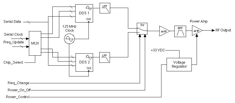
The figure above is a simplified block diagram of a high speed synthesizer developed by R. A. Wood Associates for a medical application. Some of the preliminary specifications are shown below:
- Output RF Power:
- The output RF power in to 50 ohm load shall be 3 Watts minimum
- Output VSWR
- 1.7:1, 50 Ohm reference impedance.
- Frequency Source Requirements
- The RF source shall provide 2 selectable frequencies (Frequency 1 and Frequency 2). The frequencies are selected based on the logic level applied to the Freq Change Strobe. When the Freq Change Strobe is logic 0, the output frequency shall be at Frequency 1. When the Freq Change Strobe is Logic 1, the output frequency shall be at Frequency 2.
- Frequency Range
- The output frequency range shall be 80 to 120 MHz.
- Frequency Resolution
- The frequency resolution of the source shall be less than 1 KHz
- Spurious (In-band)
- The maximum level of spurious signals within the frequency range of 60 MHz to 160 MHz shall be -30 dBc relative to the RF output signal level.
- Harmonics and out of Band Spurious
- The maximum level of harmonics and spurious signals outside the frequency range of 60 MHz to 160 MHz shall be -20 dBc.
- Digital Interface:
- Serial Interface, 2 wire, Clock and Serial Data
- Power Level Control
- Analog Input for Power Control: 0 to 10 Volts, approximately linear, to adjust RF power from 1 to 3 Watt
- Frequency Switching Time:
- Less than 5 uSec (actual performance is less than 10 nSec)
Posted by Bob Wood at 3:31 PM
Edited on: Monday, August 14, 2006 12:50 AM
Categories: 80 Consulting Examples-Archive
Edited on: Monday, August 14, 2006 12:50 AM
Categories: 80 Consulting Examples-Archive