Thursday, October 31, 2024

R. A. Wood Associates Top Level Catalog

R. A. Wood Associates has developed many RF/microwave components to support our higher level assemblies. These have been designed, built, tested and integrated into our delivered products. Since most of our products support EW missions, the parts are inherently wideband, and can be used in wideband or narrowband applications. We've created a Top Level Catalog of these components that can be downloaded.

The components include:

  • RF/Microwave Equalizers
  • RCT0050 Wideband Amplifier
  • RCT0067 Digital Attenuator
  • RCT0061 Wideband Amp/Digital Attenuator
  • RCT0075 HDR (High Dynamic Range) Gain Block
  • RCT0070 Mixer/LO Amp
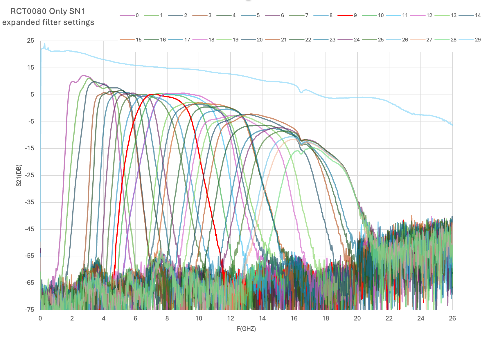
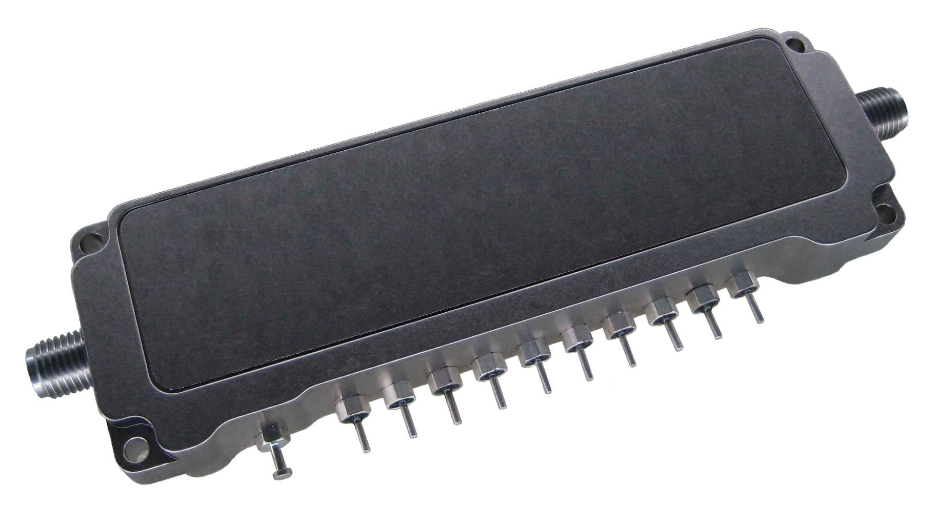
  • RCT0080 EW CFM (Configurable Filter Module)
  • Wideband Power Dividers, 8 Way and 12 Way
  • SP2T Wideband Switches
  • Extreme BW RF Amplifiers

Let us know if you would like more information about any of these products!

Posted by Bob Wood at 12:17 AM
Edited on: Friday, November 15, 2024 7:11 PM
Categories: 10 QuickNews, 20 Hardware Products-Current

Tuesday, October 24, 2023

New Equalizers added to our Website!

Hi Everyone!

We've just updated our Website with our new equalizer designs. We now have over 322 unique, high performance designs covering up to 20GHz. These designs have many different slopes and the lowest loss, best slope and return loss performance of any equalizers on the market today. We also have 4 new negative slope designs, based on customer requests. We will very soon be adding custom filtering to the Website to make it easier to find the parts you need. If you don't see a part that fits your need, just contact us at rawood-at-rawood-dot-com and let us know what you are looking for.

Posted by Bob Wood at 6:43 PM
Edited on: Wednesday, October 25, 2023 5:39 PM
Categories: 10 QuickNews, 60 Hardware Products-Archive

Friday, September 08, 2023

6U VPX Microwave Module with State of the Art Residual Phase Noise Designed and Tested

We've recently designed, built, and tested a 6U VPX microwave module for a high performance radar system with state of the art residual phase noise performance. The module was tested with our Holzworth Phase Noise Analyzer. Residual phase noise of <-155 dBc/Hz at 1 KHz offset and <-162 dBc/Hz at 10 KHz offset were acheived. Spurious levels were <-130 dBc. Internal detectors provided input and output detected power levels for Built-in-Test reporting. This module was tested using our in-house vibration, temperature, and shock qualification equipment.
Posted by Bob Wood at 7:10 PM
Edited on: Tuesday, September 19, 2023 10:27 PM
Categories: 10 QuickNews, 20 Hardware Products-Current, 40 Engineering Consulting Services-Current

Wednesday, August 16, 2023

9X8 Switch Matrix / Up Converter SN40 Delivered!

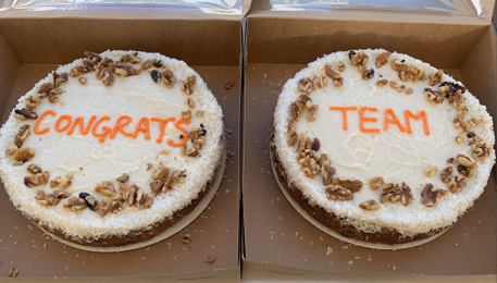
We've delivered our 40th 9X8 Switch Matrix / Up Converter. We designed and started producing these in 2018, and have made on-time deliveries on each one since then. Congrats to the team on getting these products completed on time!  
Posted by Bob Wood at 6:27 PM
Edited on: Thursday, August 17, 2023 6:26 PM
Categories: 10 QuickNews, 20 Hardware Products-Current

Monday, August 07, 2023

14 X 12 Switch Matrix / Up Converter SN22 Delivered!

We just delivered SN022 of RCT0064. This unit allows 14 microwave inputs to be switched to any of 12 Microwave outputs. This was an extremely challenging design, with custom-designed 12-Way power dividers, our own RCT0050 WB Amplifiers, custom designed SP2T Switches, 3 internal switch matrix "cubes" (2X12, 6X12, and 6X12) with blind mate interconnections, and custom designed WB Digital Attenuator/Amplifiers, all in a 3U height rack mount package.

Friday, June 16, 2023

New Design and Product Delivered: FSSDU


We've just designed and delivered a new product: First Stage Signal Distribution Unit (FSSDU). This 3U unit provides many functions, including:
  • Amplification and equalization of extremely wide RF and Microwave frequency bands
  • Distibution of bands to support many receivers and carry-on equipment
  • Combining of frequency bands to create a broad spectrum output for wideband analysis
  • Low noise figure, high dynamic range amplification to maintain the system RF signal path performance
  • This unit replaces an older unit with new hardware and expanded capability
  • Ethernet Interface
Posted by Bob Wood at 7:45 PM
Edited on: Friday, August 25, 2023 2:46 PM
Categories: 10 QuickNews, 20 Hardware Products-Current, 40 Engineering Consulting Services-Current

Thursday, June 15, 2023

New Product Designed and Delivered: BIT / DVA Assembly


We've recently designed and delivered a new 1U Height BIT (Built-in-Test) / DVA (Digital Variable Attenuators) Assembly. This unit provides:

  • Wide Microwave Frequency Band coverage across 8 inputs
  • The capability to inject BIT Signals into each microwave input to support system health testing and grooming
  • Gain Adjust and high dynamic range Amplification using our RCT0061 Wide-Band Digital Attenuator Amplifier
  • Equalization to correct negative slope across the frequency band
  • Creation of mmW BIT signals using frequency doublers
  • Ethernet Interface
This part can be used anywhere in a system to inject Built in Test signals, while still maintaining the RF path dynamic range and noise figure. It's small 1U height allows it to fit in many locations in a system.
Posted by Bob Wood at 6:55 PM
Edited on: Thursday, August 17, 2023 8:06 PM
Categories: 10 QuickNews, 20 Hardware Products-Current, 40 Engineering Consulting Services-Current

Friday, April 28, 2023

8X8 Backfit Switch Matrix / Up Converter SN 33 to be delivered

We've delivered Serial Number 25 of our 8X8 Switch Matrix / Up Converters, and are working on new orders of SN's 26-33. This is a 3U direct form, fit, and function replacement for a 6U LRU, giving the customer a modern upgrade and space savings at the same time. All deliveries have been on schedule!
Posted by Bob Wood at 5:37 PM
Edited on: Thursday, August 17, 2023 6:28 PM
Categories: 10 QuickNews, 20 Hardware Products-Current

Monday, October 31, 2022

The Millennium Edition HPOI Tuner Y2K Compliant!

Our 2000th HPOI Microwave Tuner was delivered!

In honor of the Y2K scare that was supposed to cause major world chaos on 12:00 AM, Jan 1, 2000, we have named this Tuner the "Millennium Edition", and have certified that it is Y2K complaint!
Posted by Bob Wood at 6:04 PM
Edited on: Friday, August 18, 2023 2:51 PM
Categories: 10 QuickNews, 15 Microwave Tuners, 20 Hardware Products-Current

Sunday, October 23, 2022

Solar Panels on Building 3 Helping to Make us Greener!

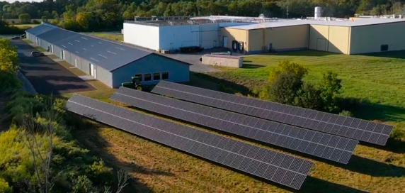
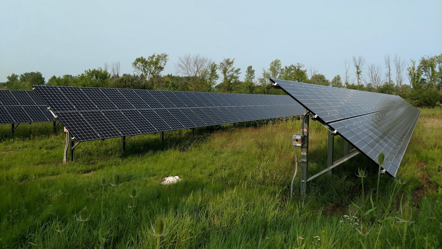
We have the 2nd set of solar panels installed on the roof of our 3rd building. These panels more than double the capacity of the first set of ground mounted panels. In some months, the solar panels have almost offset our entire electric bill!  
Posted by Bob Wood at 10:12 PM
Edited on: Friday, August 18, 2023 2:55 PM
Categories: 10 QuickNews

Wednesday, June 22, 2022

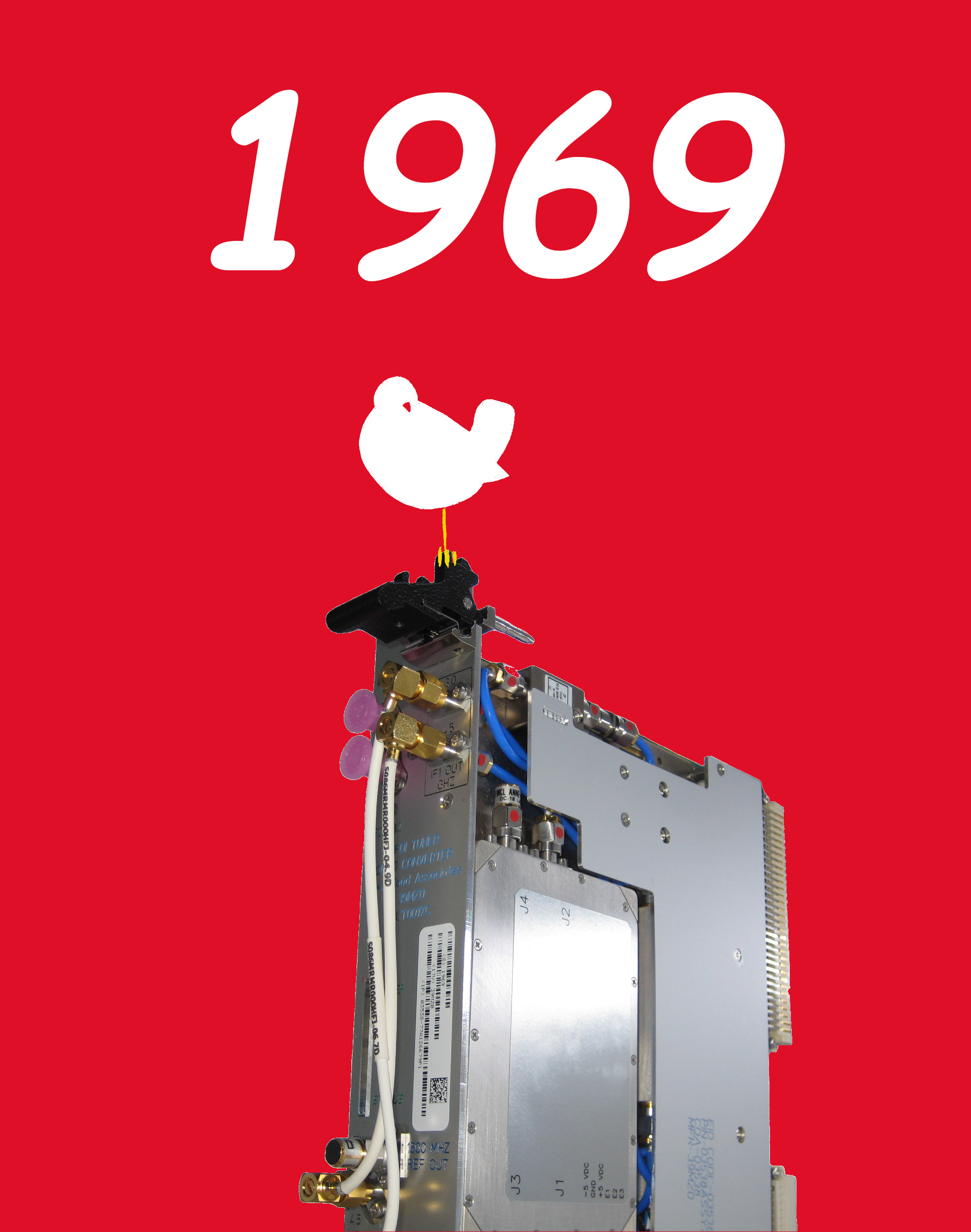
SN 1969, the Woodstock Edition of our Microwave Tuner is ready to ship!

Serial Number 1969 of our microwave tuners has been readied for shipment. In honor of the iconic year of 1969, a great moment in our history where 400,000 people attended a 4 day music festival called Woodstock with 34 of the greatest artists of the time, we are naming SN1969 the Woodstock Edition Microwave Tuner!
Posted by Bob Wood at 12:40 AM
Edited on: Sunday, October 23, 2022 10:29 PM
Categories: 10 QuickNews, 15 Microwave Tuners

Thursday, June 02, 2022

R. A. Wood Associates is Re-Certified for AS9100D / ISO 9001:2015 Quality System

On June 2, 2022, R. A. Wood Associates was re-certified for our AS9100D / ISO 9001:2015 Quality System by Perry Johnson Registrars, Inc.. We are certified for "Design and Manufacture of RF and Microwave Products". Congrats to all who worked so hard to get us through this re-certification!
Posted by Bob Wood at 10:49 PM
Edited on: Sunday, October 23, 2022 11:00 PM
Categories: 10 QuickNews

Monday, July 19, 2021

R. A. Wood Associates becomes certified for AS9100D and ISO9001:2015 Quality Management System!
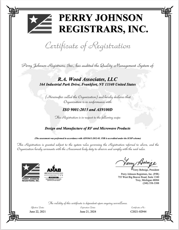
R. A. Wood Associates is now certified for AS9100D and ISO9001:2015 Quality Management for "Design and Manufacture of RF and Microwave Products". This was a huge effort undertaken by everyone in the organization. Thanks to everyone who worked tirelessly to help us get to this point!
Posted by Bob Wood at 10:38 AM
Edited on: Sunday, October 23, 2022 11:01 PM
Categories: 10 QuickNews

Saturday, October 31, 2020

Our 2nd Facility Expansion is Almost Complete!

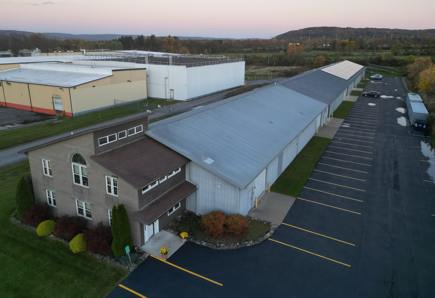
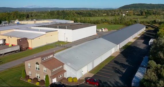
Our 2nd Addition (225' X 60', 13,500 Sq Ft) to our building is almost complete. This will give us a total of 31,000 Sq Ft of engineerring and manufacturing space, allowing us to design, manufacture, and deliver more microwave products to our customers!
Front View (addition added to the rear of the building)
Rear View and Solar Panels
Posted by Bob Wood at 2:11 AM
Edited on: Sunday, October 23, 2022 10:35 PM
Categories: 10 QuickNews

Thursday, October 01, 2020

14 X 12 Microwave Switch Matrix / Up Converter Delivered
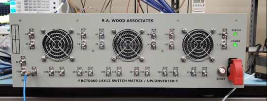
We just delivered our 1st 14 X 12 Microwave Switch Matrix / Up Converter (RCT0060). This unit allows 14 microwave inputs to be switched to any of 12 Microwave outputs. This was an extremely challenging design, with custom designed 12-Way power dividers, our own RCT0050 WB Amplifiers, custom designed SP2T Switches, and custom designed WB Digital Attenuator/Amplifiers. The whole unit is made to fit in a 3U rack mount location. Congrats to our great mechanical and electrical design, and integration and test team for developing this successful design!
Posted by Bob Wood at 11:29 PM
Edited on: Monday, August 21, 2023 2:44 PM
Categories: 20 Hardware Products-Current, 40 Engineering Consulting Services-Current

Monday, June 29, 2020

R. A. Wood Associates Receives Order for 268 Microwave Tuners for FY20

We received orders for QTY 268 Microwave Tuners for FY20. This is the result of our committment to keep our costs under control, and continuing to deliver quality products to our customer and ultimately for the US military.

Posted by Bob Wood at 3:28 PM
Edited on: Sunday, October 23, 2022 10:43 PM
Categories: 10 QuickNews

Friday, April 17, 2020

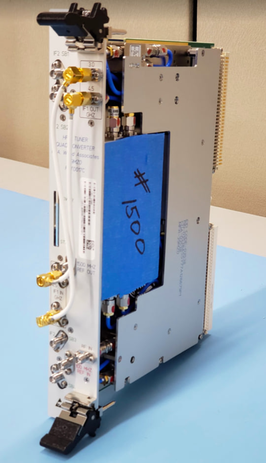
Microwave Tuner Serial # 1500 in process!

Hi Everyone!
We are marking the 1500th Microwave Tuner in production, showing Serial Number 1500 here. Congrats to our great team for working hard to get us to this amazing milestone!
We are still going strong manufacturing and shipping these now and for the forseeable future.
Posted by Bob Wood at 1:17 PM
Edited on: Sunday, October 23, 2022 10:43 PM
Categories: 10 QuickNews, 15 Microwave Tuners, 20 Hardware Products-Current

Thursday, January 23, 2020

RF Receiver Simulator RCT0053
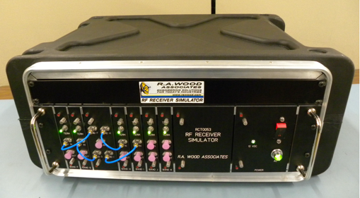
We designed and built an RF Receiver Sumiulator RCT0053, designed to simulate the front end characteristics of an EW system, from the antennas to the downstream rack equipment. We used our customer designed RCT0050 WB amplifiers in many of the 6 microwave channels.

Tuesday, October 01, 2019

Our Team gets IPC J-STD-001 Solder Training!

We had 20 people go through IPC J-STD-001 Specialist Certification Training and 9 people take J-STD-001 Hand Soldering Certification (3 days). Thanks to EPTAC, the training company, for coming into our facility to train everyone! Thank you to our great employees who took the time and effort to complete the training!

Posted by Bob Wood at 4:17 PM
Categories: 10 QuickNews

Wednesday, September 18, 2019

FY18 Tuners+ Celebration
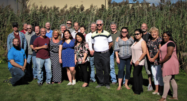
We had a great time celebrating successful deliveries of 172 FY18 Microwave Tuners, plus:
  • 1,175 equalizers
  • 7 amplifiers
  • 8 RPL0103 Low Band Modules
  • RPL0225 Up Converters
  • 8 RPL0166 Up Converters
  • 5 9X8 Switch Matrices
  • 5 8X8 Switch Matrices
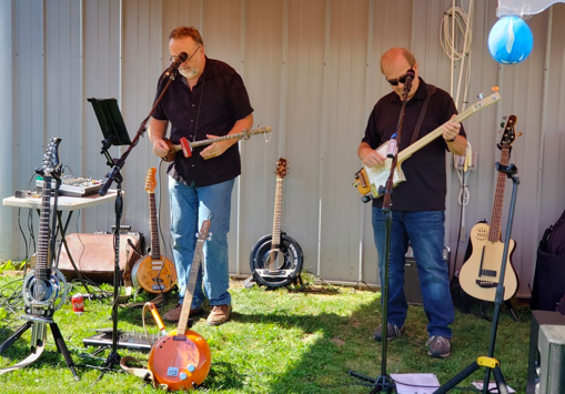
We had Dinasaur BBQ bring in the food, and the Swamp Drivers Band playing live. Thank you everyone for helping us make on-time deliveries with quality products!
 
Posted by Bob Wood at 1:27 PM
Edited on: Saturday, October 31, 2020 2:10 PM
Categories: 10 QuickNews

Sunday, September 01, 2019

More Microwave Switch Matrices / Up Converters!
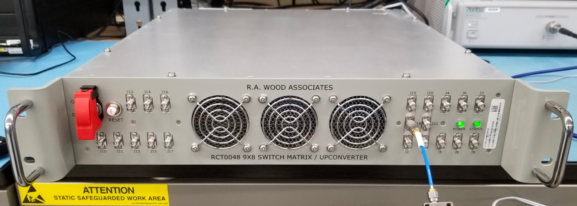
R. A. Wood Associates has received more orders for non-blocking microwave switch matrices for Naval applications. We have orders and are executing on QTY 21 9X8 Switch Matrices/Up Converters and QTY 20 8X8 Switch Matrices/Up Converters. Each of these matrices uses our own wideband power divider designs (8/9 each). The 9X8 design uses our own surface mount switches and ultra wideband (0.5 to 18 GHz) surface mount amplifier designs. Both of these products are packed into a 2U rack mount chassis design.
Posted by Bob Wood at 12:38 PM
Edited on: Saturday, October 31, 2020 2:16 PM
Categories: 10 QuickNews, 20 Hardware Products-Current

Friday, March 15, 2019

268 Microwave Tuners ordered for FY19!

R. A. Wood Associates received an order for 268 Microwave Tuners for FY19. This will bring our total orders to over 1500 Microwave Tuners, resulting in over 3000 digital/signal conditioning boards, and over 12,000 packaged microwave assemblies being assembled and tested at our facility, all with on-time delivery and keeping costs under control.

Posted by Bob Wood at 3:18 PM
Edited on: Monday, October 28, 2019 7:40 PM
Categories: 10 QuickNews, 15 Microwave Tuners, 20 Hardware Products-Current

Wednesday, October 17, 2018

New Ultra-Wideband Microwave Amplifier Available!

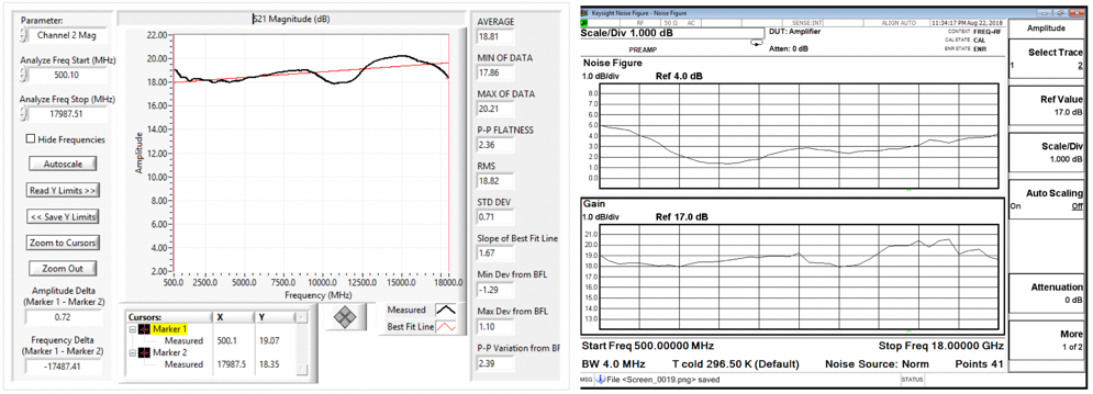
We've developed a new Ultra-Wideband Microwave Amplifier, the RCT0050, covering the frequency band of 0.5 to 18 GHz. This amplifier is built using surface mount technology, resulting in a lower production cost than traditional MIC amplifiers, with faster delivery times. Typical amplifier characteristics are:

  • ~19 dB Average Gain
  • <3.0 dB P-P Flatness
  • 22 dBm Average Pout 1 dB
  • Noise Figure ranging from <2 dB to 5.0 dB.
  • ~200 mA Current Draw from +12 V

This is a great overall amplifier for low noise, high dynamic range, wideband EW applications, or narrowband applications. More information is available from this link. Let us know if you are interested in this product!

Posted by Bob Wood at 6:51 PM
Edited on: Saturday, November 14, 2020 10:53 AM
Categories: 10 QuickNews, 20 Hardware Products-Current

Friday, August 17, 2018

Current Job Openings

We will post current job openings to the following site:

https://rawood.betterteam.com

Let us know if you would like to join our great team!

Posted by Bob Wood at 3:53 PM
Edited on: Wednesday, August 30, 2023 5:42 PM
Categories: 13 Current Job Openings

Friday, May 25, 2018

30 New Equalizers on our Equalizer WWW page!

If you haven't visited our Equalizer WWW page in a while, you'll notice we have about 30 new equalizer designs, covering different slopes and frequency bands. Have a great Memorial Day Weekend!

Posted by Bob Wood at 2:57 PM
Edited on: Friday, May 25, 2018 3:05 PM
Categories: 10 QuickNews, 20 Hardware Products-Current

Thursday, April 19, 2018

We've built our 1000th Microwave Tuner!
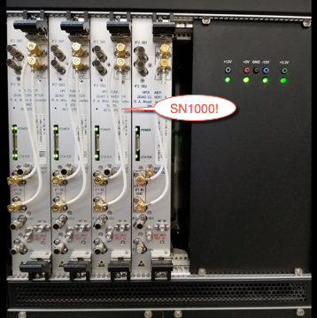
We are excited to anounce that our 1000th Microwave Tuner is in burn-in and getting ready to be shipped! What a great accomplishment for our amazing team!

We've shown our customers that we can deliver a quality product at production rates, and meet their delivery schedules. I'd like to personally thank them for giving us the opportunity to meet their expectations. Thank You! Bob Wood
Posted by Bob Wood at 6:58 PM
Edited on: Friday, July 27, 2018 6:56 PM
Categories: 10 QuickNews, 15 Microwave Tuners, 20 Hardware Products-Current

Saturday, November 11, 2017

R. A. Wood receives order for QTY 9 8X8 Microwave Switch Matrices/Up Converters!
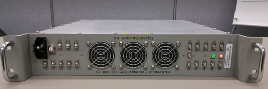
We just received an order for 9 RCT0043 Switch Matrix/Up Converters, to be used in Navy Vessels. These products allow 8 RF/microwave inputs to be routed to any of 8 RF/microwave output ports, The switch matrix is non-blocking.
The design includes:
  • Custom designed 8-way power dividers (covering a 4:1 bandwidth)
  • A low band Up Converter
  • An internal power supply
  • High Speed LVDS interface
  • High Dynamic Range RF amplifiers on inputs and outputs
  • Custom designed equalizers for slope correction, and
  • FPGA board for control and status (Built in Test) monitoring
The entire assembly is housed in a 2U rack mount assembly, saving precious rack space. The full frequency coverage is 0.5 to 18 GHz.
Posted by Bob Wood at 7:02 PM
Edited on: Friday, July 27, 2018 6:54 PM
Categories: 10 QuickNews, 20 Hardware Products-Current

Thursday, October 05, 2017

R. A. Wood Associates has a new distributor for sales to Japan, Australia, and France

We are pleased to announce that Impulse Technologies has been selected as our exclusive distributor for products purchased from Australia, France, and Japan. Please contact them directly for pricing and delivery information from the countries of Australia, France, and Japan: Sales@impulse-tech.com, www.impulse-tech.com. We are looking forward to working with Impulse Technologies. They have great service and are very responsive to customers!

Posted by Bob Wood at 4:02 PM
Edited on: Tuesday, November 12, 2024 12:34 PM
Categories:

Wednesday, June 14, 2017

Solar Arrays Up and Running

The new Solar Array is up and running, creating electricity to support our use. The Solar Array was installed to help us transition to using solar energy for all our electricity needs. This reduces our operating expenses and lowers our ecological footprint. On a good day we can create ~450 kWhours of electricity. It goes onto the power grid to credit our account if we produce more than we use. Pretty exciting!  
Posted by Bob Wood at 11:30 PM
Edited on: Friday, July 27, 2018 6:54 PM
Categories: 10 QuickNews

Wednesday, May 17, 2017

The New Building Extension is Complete

The new building extension is complete and we are making good use of the additional space. We increased our capacity by ~8800 sq ft.
Posted by Bob Wood at 11:29 PM
Edited on: Saturday, October 31, 2020 1:12 AM
Categories: 10 QuickNews

We received an order for 167 Microwave Tuners!

More exciting news that shows our continued comittment to our customers and the critical program these tuners are being used on.
Posted by Bob Wood at 12:40 AM
Edited on: Friday, July 27, 2018 7:35 PM
Categories: 10 QuickNews, 15 Microwave Tuners, 20 Hardware Products-Current

Wednesday, February 15, 2017

Inside View of New Building Extension

The new building is ready to move into. The floor is ESD coated to prevent static buildup. LED lighting is installed throughout. Radiant heat was installed in the concrete floor. Very comfortable!   
Posted by Bob Wood at 3:05 AM
Edited on: Thursday, August 17, 2023 7:34 PM
Categories: 95 Other-Archive

Wednesday, December 14, 2016

R. A. Wood Associates Receives an Order for 212 Microwave Tuners!

After a difficult negotiation to make significant cost reductions, we received an order for 212 microwave tuners. We will be delivering these at an increased rate of 24 per month. The 2 slot VME wide band microwave tuner is shown here being tested in our portable microwave test station.
Posted by Bob Wood at 11:47 PM
Edited on: Friday, July 27, 2018 7:29 PM
Categories: 10 QuickNews, 15 Microwave Tuners, 20 Hardware Products-Current, 60 Hardware Products-Archive

Tuesday, August 23, 2016

New Building Extension coming along very quickly!

We are doubling our manufacturing and engineering capacity with a new building addition. It is going up very fast, and will be ready soon to serve our wonderful current customers and future customers.
Posted by Bob Wood at 11:59 PM
Edited on: Saturday, October 31, 2020 1:57 AM
Categories: 95 Other-Archive

Friday, August 19, 2016

24 more Microwave Tuners ready to ship!


Posted by Bob Wood at 6:33 PM
Edited on: Friday, July 27, 2018 7:20 PM
Categories: 10 QuickNews, 15 Microwave Tuners, 20 Hardware Products-Current

New Equalizer designs now available!

We keep working on new designs for our customers, and improving on our earlier designs. We now have over 231 equalizer designs available, more than any other manufacturer. Various slopes over frequency ranges from DC to 28 GHz are available. You can go to our Equalizer WWW page to see what we have. Actual plots are shown for each design. If you don't see what you need, let us know, and we'll see if we can help you out.
Posted by Bob Wood at 4:32 PM
Edited on: Friday, July 27, 2018 7:20 PM
Categories: 10 QuickNews, 20 Hardware Products-Current

Saturday, February 27, 2016

New Capability to provide tight tolerance surface mount capacitors

Hi Everybody

We've recently developed the capability to automatically measure surface mount capacitors and bin them into very tight tolerance windows. We can work with 0603, 0402, and 0201 size capacitors. We can provide down to 2-2.5% tolerance capacitors for values down to 0.1 pF. These parts are typically only available in very wide tolerances (up to 50%).

This capability is very useful for filter designs, and other microwave circuit designs.

These tight tolerance capacitors can reduce or eliminate tuning typically needed to meet performance requirements.

We are going to start providing these parts to customers on a trial basis. If you are interested, please contact us to see how we can help you out!
Posted by Bob Wood at 1:24 AM
Edited on: Monday, February 29, 2016 3:27 PM
Categories: 10 QuickNews, 20 Hardware Products-Current, 40 Engineering Consulting Services-Current

Monday, February 08, 2016

New Surface Mount Rework System enhances our RF production capability

We've recently added a new Surface Mount Rework System to enhance our capability to safely and accurately replace surface mount components including RF amplifiers, mixers, FPGA's and other ball grid array parts. Another high technology tool to allow us to provide high quality, low cost production microwave assemblies using surface mount assembly processes.
Posted by Bob Wood at 1:03 AM
Edited on: Thursday, August 17, 2023 7:38 PM
Categories: 95 Other-Archive

Monday, December 21, 2015

Happy Holidays from R. A. Wood Associates

We can't let the year go by without wishing our customers, vendors, and fellow workers a wonderful Holiday and an optimistic look forward into the New Year.

Thank you everybody, and we look forward to working with each of you next year!

From all of us at R. A. Wood Associates
 
Posted by Bob Wood at 7:58 PM
Edited on: Saturday, October 31, 2020 2:34 AM
Categories: 95 Other-Archive

Tuesday, November 03, 2015

8X8 Switch Matrix / Up Converter Delivered

We delivered a new design to one of our customers: An 8X8 Microwave Switch Matrix /Up Converter. The unit allows 8 RF/microwave inputs to be routed to any of 8 RF/microwave output ports. The design includes:
  • Custom designed 8-way power dividers (covering a 4:1 bandwidth)
  • A low band Up Converter
  • An AC/DC power supply
  • High Speed LVDS interface
  • High Dynamic Range RF amplifiers on inputs and outputs
  • Custom designed equalizers for slope correction, and
  • FPGA board for control and status (Built in Test) monitoring
The entire assembly is housed in a 2U rack mount assembly, saving precious rack space. The full frequency coverage is 0.5 to 18 GHz.
Posted by Bob Wood at 12:11 AM
Edited on: Friday, July 27, 2018 7:30 PM
Categories: 10 QuickNews, 20 Hardware Products-Current, 40 Engineering Consulting Services-Current

Friday, September 18, 2015

We've moved to a new location!

We've moved to a new and better location. Our new address is:

R. A. Wood Associates, LLC
164 Industrial Park Drive
Frankfort, NY 13340

We are very excited about this move to larger space, more efficient manufacturing work flow, and easier access for our customers and employees.
Posted by Bob Wood at 4:33 PM
Edited on: Friday, July 27, 2018 7:08 PM
Categories: 10 QuickNews

Monday, August 24, 2015

R. A. Wood Associates receives a new production order for 168 wideband Microwave Tuners

We've received another production order for wideband Microwave Tuners. We will be delivering these at a rate of 17/month.

Posted by Bob Wood at 2:27 AM
Edited on: Saturday, September 19, 2015 2:46 AM
Categories: 10 QuickNews, 15 Microwave Tuners, 20 Hardware Products-Current

Wednesday, April 15, 2015

R. A. Wood Associates receives contract to build 8X8 microwave switch matrices

We received an order to design and build QTY 3 8X8 microwave switch matrices. The unit allows 8 RF/microwave inputs to be routed to any of 8 RF/microwave output ports. In another viewpoint, each of 8 RF/microwave output ports can select any of 8 RF/microwave input ports for down stream processing. The design includes:

  • custom designed 8-way power dividers (covering a 4:1 bandwidth),
  • a low band Up Converter,
  • an AC/DC power supply,
  • LVDS interface,
  • RF amplifiers on inputs and outputs,
  • custom design equalizers for slope correction,
  • FPGA board for control and status (Built in Test) monitoring

The entire assembly is housed in a 2U rack mount assembly, saving precious rack space. The full frequency coverage is 0.5 to 18 GHz. The first unit will be delivered in September 2015.

Monday, January 12, 2015

Great News! 2nd Party Survey for ISO 9001:2008 and ESD Certification Approved!

Great News again! R. A. Wood Associates has received approval by Lockheed Martin for ISO 9001:2008 Quality Management System (2nd Party survey), and Electrostatic Discharge Control (ESD). This "no exceptions" survey endorses our quality process and procedures. Thanks to everyone involved who helped to make this become a reality! Bob Wood
Posted by Bob Wood at 10:06 PM
Edited on: Monday, August 21, 2023 6:01 PM
Categories: 95 Other-Archive

Monday, December 22, 2014

Happy Holidays from all of us at R. A. Wood Associates!

We wish all our customers and vendors a wonderful and healthy Holiday Season. Thank you to our vendors for delivering high quality products to us on time, and thank you to our customers for letting us provide great products and services to you. We look forward to a great New Year with each of you!

Posted by Bob Wood at 11:25 PM
Edited on: Saturday, October 31, 2020 2:33 AM
Categories: 95 Other-Archive

Saturday, November 01, 2014

R. A. Wood Associates receives production order for 144 wideband Microwave Tuners

Another endorsement of our quality, great design, and determination to maintain low cost for our customer.

Thursday, September 11, 2014

New Capabilities and Accomplishments Brochure

We've created a new "Capabilities and Accomplishments" brochure. This brochure highlights our more recent accomplishments, and shows the current focus areas of our business. You can download the new Capabilities and Accomplishments pdf file. We hope this gives you a better idea of what we can possibly do to help your company succeed.

Posted by Bob Wood at 8:06 PM
Edited on: Monday, August 21, 2023 6:05 PM
Categories: 95 Other-Archive

Friday, June 27, 2014

More Microwave Tuners rolling off the Production Line!

Another 13 of our state of the art high dynamic range Microwave Tuners (with integrated synthesizers) are getting ready to be shipped (on time) to one of our customers. The shipment includes our 100th production Tuner, a very exciting milestone!

For more information, download the RCT0017 product sheet

Posted by Bob Wood at 6:38 PM
Edited on: Thursday, September 11, 2014 8:04 PM
Categories: 10 QuickNews, 15 Microwave Tuners, 20 Hardware Products-Current

Tuesday, June 17, 2014

RPL0045 Low Band Modules: More orders in process!

LB Modules, Serial No's 32-43, built using our Extreme BW RF Amplifier designs, are on order and being built for our customer. These modules are being deployed in a subsystem on board U.S. Navy submarines.
Posted by Bob Wood at 3:15 PM
Edited on: Friday, July 25, 2014 3:19 PM
Categories: 10 QuickNews, 20 Hardware Products-Current

Wednesday, May 14, 2014

Some Feedback from One of our Equalizer Customers:

"Our experience with R. A. Wood Associates was beyond our expectations. The willingness to deliver a product in such a short time period was very refreshing. The product worked exactly as described and met our needs. We will very likely buy again."

We are always pleased to hear good feedback about our products and services!

Monday, October 07, 2013

RF and Microwave Courses Currrently on Hold

Hello Everybody

We are currently under intense pressure to deliver hardware within very tight schedule constraints. Unfortunately, this means we will have to temporarily suspend the RF and Microwave Courses until further notice.

If you would like to be placed on the list to be notified when future courses are available, please send us an e-mail and we'll add you to our list.

Thank you for your patience, and we hope to see you at a future course!
Bob Wood

Sunday, October 06, 2013

Production Orders for High Dynamic Range Wideband Tuner/Quad Converters

We are currently under contract to build 109 high dynamic range Wideband Tuners/Quad Converters over the next year. These devices feature:
  • The highest dynamic range microwave tuners in the industry
  • Maximum use of surface mount RF/Microwave assemblies for frequencies up to 18 GHz
  • 4 output IF bands to provide 1.5 GHz instantaneous bandwidth
We are bringing all our computer automated test software and hardware design expertise into this program to maximize our productivity and provide the lowest cost product to our customer.

This is the improved RCT0017B Wideband Tuner/Quad Converter, which is the result of 18 months of development improvements from our original RCT0017 model.

Posted by Bob Wood at 12:24 AM
Edited on: Friday, July 27, 2018 7:30 PM
Categories: 10 QuickNews, 15 Microwave Tuners, 20 Hardware Products-Current

Thursday, August 22, 2013

RPL0045 Low Band Modules: 20 More Deliveries!

20 more LB Modules, built using our internal amplifier designs, were built and tested and delivered to our customer on time! These modules are being deployed in a subsystem on board U.S. Navy submarines.
Posted by Bob Wood at 12:39 PM
Edited on: Friday, July 25, 2014 3:16 PM
Categories: 60 Hardware Products-Archive

Thursday, June 13, 2013

Automated RF/Microwave Test Station

A 2nd general purpose automated RF/Microwave Test Station was designed and built by R. A. Wood Associates. The purpose was to provide automated test and device characterization to:
  • 10 MHz - 18 GHz test range as built with capability to expand up to 20 GHz
  • Reduce manual test time
  • Eliminate errors in recording of results
  • Increase throughput
  • Eliminate manual RF connections and DC connections in mid-test
  • Provide automated test reports
  • Save test results electronically in a database structure
The Automated RF/Microwave Test Station includes:
  • DAQ/Switch Unit
  • Three programmable power supplies
  • Signal Generator
  • Spectrum Analyzer
  • Table/Work Surface
  • Rack Mount Computer
  • Monitor
  • LabVIEW Software utilities to support setting up the Spectrum Analyzer and Signal Generator, retrieving data from the Spectrum Analyzer, controlling the RF Switch/DIO Box and other measurement equipment in the Test Station
  • Storage drawer
  • Custom RF Switch/DIO Box provides:
    • Automated RF Switching to 1 of 6 RF Inputs and 1 of 6 RF Outputs up to 18 GHz
    • Oscillators needed for Test Units
    • Digital I/O to control and read digital signals to/from Test Units
    • Relay Switching to read Resistances and switch DC Power to Test Units
 
Posted by Bob Wood at 12:49 AM
Edited on: Monday, October 07, 2013 7:49 PM
Categories: 10 QuickNews, 20 Hardware Products-Current, 30 LabVIEW Projects-Current

Monday, May 06, 2013

New Bench Top RF Switch Digital I/O Test Interface Box

The RF Switch/DIO Box is a custom designed LRU that provides:
  • Automated RF Switching to 1 of 6 RF Inputs and 1 of 6 RF Outputs up to 18 GHz
  • Oscillators needed for Test Units
  • Digital I/O to control and read digital signals to/from Test Units
  • Relay Switching to read Resistances and switch DC Power to Test Units
  • Bench top or Rack mount
We have built 5 of these for our own automated test stations. The design is universal and can be used for multiple test applications.
Posted by Bob Wood at 12:29 PM
Edited on: Monday, October 07, 2013 7:20 PM
Categories: 10 QuickNews, 20 Hardware Products-Current, 40 Engineering Consulting Services-Current

Tuesday, April 30, 2013

RPL0103 Low Freq Wide Band RF SubAssembly Designed and 17 Delivered

RPL0103 Low Frequency Wide Band RF SubAssembly features:
  • Wide Freq bandwidths ~DC-3GHz
  • Uses New R.A.Wood Associates designed amplifiers with new 50% smaller M06 amplifier packages
  • Used as part of a Subsystem, deployed on Navy vessels
  • 14 built and delivered on time
  • Provides 9 output ports for downstream equipment
Posted by Bob Wood at 2:55 PM
Edited on: Monday, August 21, 2023 6:03 PM
Categories: 60 Hardware Products-Archive, 95 Other-Archive

Tuesday, March 05, 2013

R. A. Wood Associates is approved for ISO 9001:2008 Quality Management System (2nd Party) and ESD Control!

Great News! R. A. Wood Associates has received approval by Lockheed Martin for ISO 9001:2008 Quality Management System (2nd Party survey), and Electrostatic Discharge Control (ESD). This puts us in a better position to deliver the highest quality products to our customers. Thanks to everyone involved who helped to make this become a reality! Bob Wood


Posted by Bob Wood at 4:10 PM
Edited on: Monday, August 21, 2023 4:51 PM
Categories: 95 Other-Archive

Friday, February 22, 2013

Equalizer Product Line Keeps Growing and Expanding!

We keep improving and adding to our lineup of available equalizer products. We currently have over 155 low loss equalizers designs with more to come. Each design is unique with a range of choices of various slopes, along with a mixture of different frequency bands from 5 kHz to 20 GHz. We can provide a selection of male and female combinations of connectors on the inputs and outputs. We'll keep updating the equalizer main page as we get more designs completed, so feel free to stop by again, or ask us if we don't have what you are looking for.
Posted by Bob Wood at 2:53 PM
Edited on: Friday, August 19, 2016 6:45 PM
Categories: 60 Hardware Products-Archive

Monday, June 04, 2012

Available Now! SimpleCycle Crystal Oscillators

We have officially released a new line of SimpleCycle crystal oscillators. These are temperature compenstated crystal osciillators in a very small package with +5 Volt DC in, and an SMA output connector. The key features include:

  • Small package size: 1.06" X 0.92" X 0.37"
  • 4 through-holes for mounting
  • Easy connections: +5V DC in, SMA out
  • Custom frequencies available from 40 MHz to 1.4 GHz
  • Frequency accuracy at +25C: < +/-1 ppm
  • Internally temperature compensated: < +/-1 ppm from -20C to +70C
  • Aging: < +/-3 ppm first year, < +/-1 ppm/year thereafter
  • Sine wave outputs (initially)

We will be working to supply these with very quick turnarounds. For more information see our SimpleCycle Oscillator page, or contact us.

Posted by Bob Wood at 7:35 PM
Edited on: Monday, October 07, 2013 7:22 PM
Categories: 10 QuickNews, 20 Hardware Products-Current, 40 Engineering Consulting Services-Current

Friday, March 30, 2012

New Quad/WB Up Converter and WB/Quad Down Converter Designs Developed and Delivered

Our Wideband Down Converter and Up Converter pair offer:

  • Frequency Coverage: 6 - 18 GHz
  • For applications employing Digital RF Memories (DRFM's) for coherent electronic countermeasures
  • Coherent system synchronized to a 100 MHz reference
  • Independent synthesizers in Down and Up Converters
  • Can be configured as independent Down and Up Converters, or as a coherent set for countermeasures or similar applications
  • Control and Status: VME A24 D32

Down Converter Features:

  • Single Unit Form Factor: 6U 2 Slot Design
  • Input Dynamic Range: -60 to +2 dBm
  • Input 1 dB Compression Point: >+6 dB
  • Noise Figure: 21 dB
  • Gain: 10 dB average
  • Phase Noise: -146 dBc/Hz @ >20 MHz Offset
  • Second IF's: Four outputs at 750 MHz, 375 MHz wide, providing 1.5 GHz instantaneous bandwidth
  • Designed to drive 1 GHz Digitizers linearly up to +12 dB

Up Converter Features:

  • Four inputs at 750 MHz, 375 MHz wide, providing 1.5 GHz instantaneous bandwidth across 6 - 18 GHz
  • Form Factor: VME 6U 2 Slot Design
  • High Input Dynamic Range: -55 to 0 dBm
  • Phase Noise: -146 dBc/Hz @ >20 MHz offset
  • Tuning Speed: 1 uSec
  • Noise Figure: 31.5 dB max
  • Input 1 dB Compression Point: >+2 dBm
  • Gain: 1 dB average
 

Monday, January 30, 2012

High Dynamic Range Microwave Tuner Designed and in Production

We haven't posted in a while. It's because we've been crazy busy. Our newest product, the RCT0017 WB Tuner and Quad Converter, has been under development over the past 2 years, and is now available. We've designed this from the ground up to meet state of the art high input compression point, low phase noise, fast tuning speed, wide dynamic range, and wide instantaneous bandwidth requirements. A quick overview of the specifications:

  • Frequency Coverage: 2-18 GHz
  • First IF’s: 2.2-3.8 GHz, 3.8-5.3 GHz, available simultaneously
  • Second IF’s: 4 outputs at 750 MHz, 375 MHz wide, providing 1.5 GHz instantaneous bandwidth across the First IF’s
  • Input 1 dB Compression Point: >+6 dBm
  • Noise Figure: 21 dB
  • Input Dynamic Range: -60 to +2 dBm
  • Gain: 10 dB average
  • Tuning Speed: <1 uSec
  • Frequency Step Size: 375 MHz
  • Phase Noise: -150 dBc/Hz @ 10-20 MHz Offset
  • Form Factor: VME 6U 2 Slot Design
  • Control and Status: VME A24 D32
  • Designed to follow an Low Noise Front End with Approximately 30 dB ENR
  • Designed to drive 1 GHz Digitizers linearly up to +12 dBm

A brief data sheet can be downloaded from this link

Posted by Bob Wood at 12:44 PM
Edited on: Monday, August 21, 2023 6:05 PM
Categories: 60 Hardware Products-Archive, 80 Consulting Examples-Archive, 95 Other-Archive

Wednesday, January 18, 2012

New Quad Converter Designed and Delivered

We designed and built for production a 4 channel Quad Converter. Our Quad Converter design features:
  • 2 Input IF's from 2.2-5.3 GHz, available simultaneously
  • Output IF's: 4 outputs at 750 MHz, 375 MHz wide, providing 1.5 GHz instantaneous bandwidth across the input IF's
  • Control and Status: VME Interface A24 D32 and UART Serial Interface
  • Designed to drive 4 1 GHz Digitizers linearly up to +12dBm
  • 5 custom surface mount RF assemblies mounted to an aluminum plate
  • Separate multilayer circuit board accommodates power conditioning, FPGA signals and VME interfacing
  • Form Factor: VME 6U 1 Slot Design
  • RF Connector Interface: SMA
This is a very complex design with very high density surface mount assemblies. Surface mount assemblies are built using pick and place machines at a contract manufacturer. Automated RF test rack, fixtures and software has been designed at R. A. Wood Associates.

Wednesday, December 14, 2011

RCT0017 Automated RF/Microwave Test Station Designed, Built, and In Service

An automated RF/Microwave Test Station was designed and built by R. A. Wood Associates. The purpose was to provide automated test and device characterization to:
  • Reduce manual test time
  • Eliminate errors in recording of results
  • Increase throughput
  • Eliminate manual RF connections and DC connections in mid-test
  • Provide automated test reports
  • Save test results electronically in a database structure
This automated test station reduced product test time from 24 hours of semi-automated testing down to approximately 2 hours. The RCT0017 Automated RF/Microwave Test Station includes:
  • DAQ/Switch Unit
  • Three programmable power supplies
  • Signal Generator
  • Spectrum Analyzer
  • Custom RF Switch/DIO Box
  • Table/Work Surface
  • Rack Mount Computer
  • Monitor
  • LabVIEW Software utilities to support setting up the Spectrum Analyzer and Signal Generator, retrieving data from the Spectrum Analyzer, controlling the RF Switch/DIO Box and other measurement equipment in the Test Station
  • Storage drawer
 

Monday, November 14, 2011

LB RF Receiver Simulator Designed and Delivered

A LB RF Receiver Simulator was designed to simulate the RF front end of a submarine periscope subsystem. The noise figure, gains, and dynamic ranges were designed to simulate the actual subsystem. The amplifiers were custom designed and equalized by R. A. Wood Associates to cover a wide bandwidth from ~DC to 3 GHz. A variable attenuator allowed the output noise floor to be adjusted in 1 dB steps.
Posted by Bob Wood at 7:52 PM
Edited on: Wednesday, October 09, 2013 12:15 PM
Categories: 10 QuickNews, 20 Hardware Products-Current, 40 Engineering Consulting Services-Current

Monday, October 10, 2011

Celebrating the Successful Delivery of EDM WB Tuners/Quad Converters!

We celebrated the successful delivery of EDM WB Tuners/Quad Converters with a Fall Cruise in the Adirondacks. Thanks to everybody who really worked hard to help us make a high quality product with on-time deliveries to our customer! From left to right: Sean, Bob, Nancy, Pat, Gerard, Al, Anne, Lorraine, Butch, Jim, Rusty, Mark, Dave, Bob, and Tim.
Posted by Bob Wood at 3:48 PM
Edited on: Monday, August 21, 2023 6:02 PM
Categories: 95 Other-Archive

Monday, December 20, 2010

2nd Test Station Delivered to NAVSEA NSWC

We designed and built a 2nd (different) Automated RF Test Station for NAVSEA NSWC, which was delivered to Crane, Indiana. This Test Station contains many state of the art features and equipment, including:
  • Tektronix RSA6120A Real Time Spectrum Analyzer
  • An R. A. Wood Associates custom designed Test Set Load Box, capable of handling 50W loads
  • Rack mount computer, keyboard, and monitor with digital I/O, GPIB interfaces
  • A PXI chassis with fiber optic interface, digital I/O, serial interfaces, temperature monitors, and GPIB interface
  • LabVIEW Software utilities to support setting up the Real Time Spectrum Analyzer, retrieving information from the Real Time Spectrum Analyzer, controlling the Test Set Load Box, and controlling other measurement equipment in the Test Station
The customer wanted this delivered before the holiday, so we rented a delivery truck and spent several days driving it out and setting it up for the customer at their facility. They were very pleased with our commitment to deliver the station on time!


Saturday, May 08, 2010

New Equalizer Designs added to our Product Line

We've released some new equalizer designs in the past few months:
Part Number Start Freq (GHz) Stop Freq (GHz) Full Band Slope
REQ-M02-F0.5-18.0-S10.5 0.5 18.0 10.5
REQ-M02-F0.5-18.0-S9.0 0.5 18.0 9.0
REQ-M02-F0.5-18.0-S17.5 0.5 18.0 17.5
REQ-M02-F1.0-8.0-S3.0 1.0 8.0 3.0
REQ-M02-F1.0-8.0-S2.0 1.0 8.0 2.0
REQ-M02-F8.0-18.0-S3.0 8.0 18.0 3.0
REQ-M02-F0.1-1.0-S38.0 0.1 1.0 38.0
REQ-M02-F0.1-1.0-S15 0.1 1.0 15.0

For more information and test results, visit or "Equalizers on Demand" WWW page. If you don't see a design that fits your needs, please call us and we'll try to develop a design that meets your requirements. Thanks for all your support, equalizer users!

38 dB slope equalizer
Posted by Bob Wood at 11:42 PM
Edited on: Monday, October 07, 2013 9:52 PM
Categories: 20 Hardware Products-Current

Test Station Delivered to NAVSEA NSWC

We delivered a Test Station to NAVSEA Naval Surface Warfare Center (NSWC) in Crane, Indiana. The Test Station contains many state of the art features, including:

  • The latest Agilent Network Analyzer (PNA-X Series)
  • A 10-port Extension for measuring multi-port S-parameters
  • An R. A. Wood Associates custom-designed RF Load Box/Chassis for testing high power RF devices
  • Rack mount computer, keyboard, and monitor with digital I/O, GPIB interfaces
  • A PXI chassis with fiber optic interface, digital I/O, serial interfaces, temperature monitors, and GPIB interfaces
  • LabVIEW Software utilities to support setting up the Network Analyzer, retrieving S-parameters from the Network Analyzer, controlling the RF Load Box, and controlling other measurement equipment in the Test Station

This was a very exciting project, and we really enjoyed working with our customer on this program. The complete project was delivered within 7 months of the order being placed. Great job everybody!

 
Posted by Bob Wood at 3:48 PM
Edited on: Wednesday, October 09, 2013 12:05 PM
Categories: 10 QuickNews, 20 Hardware Products-Current, 30 LabVIEW Projects-Current, 40 Engineering Consulting Services-Current

Monday, April 05, 2010

mmW Equalizers Designed and Built for our Customer

One of our customers had a need for a mmW equalizer to help offset a 7 dB negative slope across a 26.0 to 40.0 GHz band. We looked far and wide to see if there were any available components out there in the industry that we could buy as an off-the-shelf part, or have someone develop for us.
We could not find any available parts. So we took on the task ourselves to design a mmW equalizer with a 7 dB positive gain slope. This is just another example of how we can break new ground to come up with designs that are needed by our customers when they are not otherwise available.
The equalizer was installed in the system, and the 7 dB negative slope was flattened out. See before and after pictures below. Another exciting success story!
 
System RF Path Gain before equalization (26-40 GHz): System RF Path Gain after equalization (26-40 GHz):
 
Posted by Bob Wood at 11:55 PM
Edited on: Monday, October 07, 2013 9:50 PM
Categories: 40 Engineering Consulting Services-Current

Friday, March 26, 2010

Painless Extraction Scriptor 1.0 Released

We have released a new Software Product, called Painless Extraction Sciptor (Version 1.0). This program combines the data extraction and analysis capabilities of Painless Extraction & Painless Extraction Noise Figure with a new Custom Dialog Utility and an External Program Caller in an easy to use interface to automate testing through scripting. This program enables the user to construct script files that will call Painless Extraction, Painless Extraction NF, Custom Dialog Boxes, and External Programs. Use these capabilities in combination to create customized automated testing procedures. For more information, please visit our software download page.
Now you can automate Network analyzer, Scalar Analyzer, and Noise Figure measurements, and automatically create test reports for production testing! The custom dialog boxes can be used to guide test personnel through the testing process. External programs can be used to control devices prior to collecting measurements from the test equipment. We'll be providing more documentation about this program through our various software and support wiki's.
Posted by Bob Wood at 4:42 PM
Edited on: Monday, October 07, 2013 9:50 PM
Categories: 35 Software Products-Current

Monday, March 22, 2010

New Update (2.2) for Painless Extraction Released

We've released a new version of Painless Extraction (2.2) today. This release includes many new features, including:

  • Compatibility with HP 8575d Scalar Analyzers
  • Compatibility with new Agilent PNA Network Analyzers (will be released in Version 2.2.1 very shortly)
  • A new graphical interface panel with plots, statistics, and a pass/fail report, all on the same page
  • Capability to be called from Painless Extraction Scriptor, which will allow Painless Extraction to be called remotely from script files (stay tuned for the release of Painless Extraction Scriptor coming soon)
  • A self contained macro capability, where multiple plots can be printed with limits. A great way to create a quick test report for each part tested.

Please feel free to visit our software information page for more information. As always, your feedback and suggestions are always welcome!

Posted by Bob Wood at 3:10 PM
Edited on: Monday, October 07, 2013 9:51 PM
Categories: 35 Software Products-Current

Tuesday, December 22, 2009

Happy Holidays from all of us at R. A. Wood Associates!

We would like to thank all our customers and clients for allowing us to help them out over the past year. We wish each of you a wonderful holiday season, and a prosperous and healthy New Year! From all of us at R. A. Wood Associates.
company picture  
Sean, Bob, Marge, Nancy, Al, Amelia, Lorraine, Pat, Dave, Rusty, and Ray (hiding).
Posted by Bob Wood at 12:42 AM
Edited on: Monday, October 07, 2013 7:25 PM
Categories: 95 Other-Archive

Saturday, October 31, 2009

LB Modules SN #10 and 11 Ready for Delivery!

Our 10th and 11th LB RF modules, containing our Extreme BW RF amplifiers, have been built, and tested, ready for delivery to our customer.

These modules will be used in our customer's systems, which will be installed on board Navy vessels.

LB RF Module SN 11
Posted by Bob Wood at 11:24 PM
Edited on: Monday, October 07, 2013 7:30 PM
Categories: 20 Hardware Products-Current

Tuesday, October 06, 2009

SpurFinder 3.5.2 Update Released

Spurfinder Cont/Single Run Button We've updated SpurFinder to version 3.5.2. This update fixed a user interface bug: When the program was initially opened, the "Continuous Run/Single Run" selector was hidden from the user interface. This selector didn't reappear until the user opened a "Multi Scenario Script File" from the file menu, and then closed the file. This may have caused some confusion in using the program, which we apologize for. The update is free and can be obtained by downloading the SpurFinder installation files from our Software Download Page. Previously registered software will still be registered during the installation.
Posted by Bob Wood at 8:17 PM
Edited on: Monday, October 07, 2013 9:51 PM
Categories: 35 Software Products-Current

Monday, October 05, 2009

ESSU SN3 Delivered

We've delivered the third Electronics Support Switching Uint (ESSU) for one of our customers (ahead of schedule!). This was another set of hardware slated to to be installed on a Navy Vessel. The ESSU is shown here with the cover removed, looking from the back. All RF components are mounted on both sides of a center RF plate. Shown are RF amplfiers, equalizers, attenuators, RF switches, cabling, FPGA card, and rear connectors (21 RF connectors, 12 video/75 ohm connectors, Audio, Power).

For additional information, please visit our ESSU information page.

ESSU SN3 with Cover off  
Posted by Bob Wood at 1:17 AM
Edited on: Thursday, August 17, 2023 6:49 PM
Categories: 40 Engineering Consulting Services-Current, 60 Hardware Products-Archive, 95 Other-Archive

Tuesday, September 29, 2009

R. A. Wood Associates awarded contract from NSWC Crane Division

R. A. Wood Associates has been awarded a contract from Naval Surface Warfare Center (NSWC), Crane Division. The contract involves designing and delivering an automated test rack consisting of:

  • A 40U rack with rack mount PC, work table, LCD monitor, GPIB controller cards,
  • A state of the art Vector Network Analyzer (VNA) with 10 port extension
  • A PXI chassis with PXI cards providing thermocouple temperature measurement, serial ports, 2 X 96 digital I/O signals
  • A custom designed RF Load Box for testing up to eight transmitter/receiver modules, capable of providing 50 Watts of RF power
  • Custom designed software for controlling the Load Box and the VNA equipment

We are fortunate to be able to work with Viewpoint Systems on this contract.

This contract was won on a competitive bid, and our solution was selected out of many other submissions. We are very excited about the opportunity to work with NSWC Crane Division!

TSDMS Rack drawing  
Posted by Bob Wood at 10:19 PM
Edited on: Tuesday, October 08, 2013 5:10 PM
Categories: 60 Hardware Products-Archive, 70 LabVIEW Examples-Archive, 80 Consulting Examples-Archive

Thursday, August 27, 2009

JBU RF Plate SN3 Delivered

JBU RF Plate SN3
JBU RF Plate SN3 was delivered to our customer (ahead of schedule!). The RF Module was designed to provide wideband gain, equalization, and Built-in-test (BIT) injection between two very long RF cable runs (between an Antenna Assembly and below decks receivers). The gain and equalization was needed to preserve the RF path noise figure and dynamic range performance through the long cable run.
All RF test data (gain, slope, flatness, return loss, input 1 dB compression point, and noise figure) was collected using our in house test equipment and our in house automated RF test software (Painless Extraction, Painless Extraction Noise Figure, and RFSpecTest). Mechanical parts were fabricated externally from our SolidWorks created mechanical drawings, and chem-film treated with Iridite (MIL-C-5541E Class 3) to prevent corrosion.
Posted by Bob Wood at 9:40 PM
Edited on: Monday, August 21, 2023 5:59 PM
Categories: 60 Hardware Products-Archive, 95 Other-Archive

Friday, August 21, 2009

RF Receiver Simuator SN4 Delivered

RF Receiver Simualtor SN4 We've delivered our fourth RF Receiver Simulator, and our 6th of a family of Receiver Simulator products. The simulators are designed to represent the RF front end (noise figure, gain compression point, and intercept point) of a complex EW system, to allow testing, verification and validation of the EW system back end, without requiring the expensive front end components.

If you have a need for one of these types of products, please contact us.
Posted by Bob Wood at 8:46 PM
Edited on: Monday, October 07, 2013 7:27 PM
Categories: 10 QuickNews, 20 Hardware Products-Current

Wednesday, July 08, 2009

Extreme BW RF Amplifier extended to 3 GHz for Direct Laser Modulation Application

We've extended the frequency range of our extreme BW RF Amplifier from 5 KHz to the upper end of 3 GHz. We customized the input equalizer to create a very flat gain response across the entire band. This amplfier was used for a direct laser modulation application. The measured performance was:
  • Average Gain: 16.31 dB
  • Slope: 0.53 dB
  • P-P Flatness: 0.83 dB
  • Min Gain(Low Freq): 15.30 dB
  • Max Input Return Loss: -13.02 dB
  • Max Output Return Loss: -9.99 dB
  • Average 1 dB Output Comp Point: 20.7 dBm
  • Min 1dB Output Comp Point: 19.97 dBm
  • Noise Figure at Low Freq: ~12.8 dB
  • Noise Figure at High Freq: ~ 5.77 dB

More information is available from our Extreme BW RF Amplifier page. Let us know if you are interested in this product line! Bob Wood.

Posted by Bob Wood at 2:07 PM
Edited on: Monday, October 07, 2013 7:27 PM
Categories: 10 QuickNews, 20 Hardware Products-Current, 40 Engineering Consulting Services-Current

Thursday, May 28, 2009

RF Receiver Simulator Delivered

We've delivered another RF Receiver simulator to one of our customers. This unit simulates the RF front end characterisitcs (noise figure, gain, dynamic range) of an EW system, so the customer can connect it to their back end system and validate full system end to end performance (system sensitivity, etc), without requiring the expensive front end components. Frequency coverage goes from 10 MHz to 40 GHz on this unit.

If you have a need for one of these types of products, please contact us.
Posted by Bob Wood at 2:43 PM
Edited on: Monday, October 07, 2013 7:28 PM
Categories: 10 QuickNews, 20 Hardware Products-Current, 40 Engineering Consulting Services-Current

Sunday, March 01, 2009

Automated RF/Microwave Test Stations designed and delivered

We've been very busy this past year. Over the last 8 months, our super qualified staff have accomplished the following:
  1. Developed automated test software for a complex RF/digital board providing RF receive, transmit, and digital signal processing functions
  2. Modified/retrofitted 12 automated test stations to test this complex RF/digital board
  3. Developed automated test software to test a LRU chassis, including point to point wiring and DC power supply checks
  4. Modified/retrofitted 2 automated test stations to test the LRU chassis
  5. Developed automated test software for a high frequency radar receiver/transmitter board, including a waveguide interface
  6. Modified/retrofitted 1 automated test station to test the high frequency radar receiver/transmitter board
  7. Developed automated test software for an IF frequency radar receiver/transmitter board
  8. Modified/retrofitted 1 automated test station to test the IF frequency radar receiver/transmitter board
Auomated RF Test Station
How can we help your company improve your manufacturing efficiencies with automated test stations and software?

Wednesday, February 04, 2009

RF and Wireless Courses set up for 2009

We've finally set up our courses for 2009. We appreciate the patience people have shown while we were setting up this schedule. A quick summary of the courses and locations:

  • Introductory RF and Microwaves, presented by Bob Wood
  • RF Power Amplifiers, Classes A-S, presented by Nathan Sokal
  • RF and Microwave Receiver Design, presented by Bob Wood

The courses will be presented in:

  • Baltimore, MD in May 2009
  • Syracuse, NY in September 2009
  • Philadelphia PA in November 2009

More information can be found at http://www.rawood.com/seminars. We hope to meet you at one of these courses! Thanks again for your patience.
Bob Wood

Posted by Bob Wood at 1:14 AM
Edited on: Monday, October 07, 2013 7:26 PM
Categories: 90 RF and Microwave Courses-Archive

Thursday, December 18, 2008

LB RF Amplifier Modules delivered

Using our Extreme BW RF amplifiers, we designed, built, and tested 7 LB RF amplifier modules for one of our customers. Our customer's original vendor failed to deliver their amplifier products and meet the requirements. So we stepped in and helped them meet their delivery schedules. These modules were made to "drop in" to our customer's modules.

These modules will be used in our customer's systems, which will be installed on board Navy vessels.

A full set of test data was provided for each LB RF Amplifier Module delivered. Our automated RF test software (RFSpecTest and Painless Extraction) helped to quickly capture the test results and create the test reports.

LB RF Amplifier Rf PLAte
Posted by Bob Wood at 1:08 AM
Edited on: Tuesday, October 08, 2013 4:27 PM
Categories: 60 Hardware Products-Archive, 80 Consulting Examples-Archive

Sunday, November 30, 2008

DF Antenna Assembly, designed and built by R. A. Wood Associates

Another great effort resulting in a great potential product!

R. A. Wood Associates designed and built a Direction Finding (DF) Antenna Assembly for one of our customers. The Assembly was designed, built, tested, and delivered in less than 6 months. The requirement was to develop an antenna assembly that could be used as a front end in front of a pair of COTS (Commercial Off the Shelf) receiver boards. The DF Antenna Assembly provided the capability to supply Direction Finding (DF) for incoming signals or emitters.

The DF Antenna Assembly included:
  • Capability to provide amplitude and phase DF between antenna pairs
  • 360 degree angular coverage
  • Low cost universal design (can be used with many different receivers)
  • Low noise figure RF front end (~3.5-4.0 dB)
  • Calibration injection to calibrate receiver amplitude and phase
  • Wide frequency coverage (500 MHz to 3 GHz)
  • High dynamic range
  • Digital Compass for DF Antenna Assembly pointing information
  • RF switches controlled by an Ethernet interface
More information is available from our DF Antenna Assembly www page
Posted by Bob Wood at 2:01 AM
Edited on: Wednesday, October 09, 2013 11:26 AM
Categories: 10 QuickNews, 20 Hardware Products-Current, 40 Engineering Consulting Services-Current

Monday, November 03, 2008

Equalizer Designs now extended up to 18 GHz

Hello Everybody

We've enhanced our portfolio of equalizer designs with new high frequency equalizers, with low losses all the way up to 18 GHz!

We also now have a smaller package design (M02 package).

We can now offer low loss, high linearity equalizers over the following frequency bands:

  • 5 KHz to 2.0 GHz
  • 0.5 to 8.0 GHz
  • 1.0 to 8.0 GHz
  • 1.0 to 2.0 GHz
  • 2.0 to 4.0 GHz
  • 4.0 to 8.0 GHz
  • 4.5 to 12.5 GHz
  • 4.0 to 18.0 GHz
  • 8.0 to 18.0 GHz
For more detailed information on available designs, including measured S21 ans S11 plots, and package outlines, visit our "Equalizers on Demand" product page.
Posted by Bob Wood at 10:45 PM
Edited on: Tuesday, October 08, 2013 4:26 PM
Categories: 60 Hardware Products-Archive, 80 Consulting Examples-Archive

Wednesday, October 01, 2008

Electronics Support Switching Unit (ESSU) designed, built, and tested by R. A. Wood Associates

R. A. Wood Associates designed, built, tested, and delivered 2 Electronics Support Switching Units (ESSU) to one of our customers. This was another set of hardware slated to to be installed on a Navy Vessel. The ESSU was designed to be installed between the front end (Antennas, RF amplification switching, filtering) and back end (RF processing) of a complex RF/Microwave system. The purpose of the ESSU was to allow a second front end (RF Subsystem 2) to be switched into the same back end, to make use of the RF signal processing in the back end.

Some of the major components in the ESSU are as follows:
  • Wideband RF/Microwave amplifiers
    • Our Extreme BW RF amplifier was used in this design for the low frequency, wide bandwidth RF path
  • Equalizers and attenuators to align the RF paths
    • Some vendor purchased equalizers were used
    • R. A. Wood Associates equalizers were also used where vendor equalizers were not available
  • Terminated mechanical RF switches (50 ohms)
  • Terminated mechanical RF switches (75 ohms)
  • HDRFI external RF interface to save RF connector space
  • DC power conditioning
  • FPGA card to control switches and provide Built-in-test (BIT) status
  • LED displays for BIT and switching status
  • Custom designed audio switching board
ESSU Front View  ESSU Rear View 
For additional information, please visit our ESSU information page.
Posted by Bob Wood at 6:48 PM
Edited on: Tuesday, October 08, 2013 4:26 PM
Categories: 60 Hardware Products-Archive, 80 Consulting Examples-Archive

Monday, June 30, 2008

Extreme BW RF Amplifiers

We've taken a challenge and come out on top again! We've developed an Extreme BW RF Amplifier, providing ~22 dB gain, and high dynamic range (~36 dBm Third Order Output Intercept Point) over the frequency band of 5 KHz to 2 GHz. An integrated RF package of 1.9" L X 1.3" W X 0.4" H was developed for the Extreme BW RF Amplifier and also included:

  • DC filter to suppress power supply ripple and noise
  • An input Equalizer where you can specify the full band slope desired
  • An output Resistive Power Divider for providing 2 equal RF outputs

The input Equalizer and output Power Divider can be "zeroed out" if not needed. The input Equalizer can be used to compensate for the amplifier slope and/or passive loss slopes. We can provide a variety of RF slopes in the input Equalizer. More information is available from our Extreme BW RF Amplifier page. Let us know if you are interested in this product line! Bob Wood.

Extreme BW RF Amplifier
Posted by Bob Wood at 10:53 PM
Edited on: Tuesday, October 08, 2013 4:25 PM
Categories: 60 Hardware Products-Archive, 80 Consulting Examples-Archive

Wednesday, June 25, 2008

JBU RF Plate Assemblies designed and delivered for Naval Application

R. A. Wood Associates designed, built and tested and delivered 2 "JBU RF PLate" Assemblies. These RF assemblies were used to provide wideband gain, equalization, and Built-in-test (BIT) injection between two very long RF cable runs (between an Antenna Assembly and below decks receivers). The gain and equalization was needed to preserve the RF path noise figure and dynamic range performance through the long cable run.

The exciting part for us is that this design will actually be deployed on a US Naval vessel. This is our first of several LRU's that were designed to be used on a US Naval vessel.
 JBU RF Plate 
Posted by Bob Wood at 11:09 PM
Edited on: Tuesday, October 08, 2013 4:25 PM
Categories: 60 Hardware Products-Archive, 80 Consulting Examples-Archive

Thursday, June 19, 2008

New "Equalizers on Demand" RF products available

Greetings! We've been very busy working on creating a new series of RF/microwave products: "Equalizers on Demand". "Equalizers on Demand" are wideband, low loss frequency equalizers made to provide a positive gain slope from the lower frequency to the upper frequency. These equalizers are designed to flatten out slope caused by long cables or other passive losses, or amplifier negative gain slopes. We have developed a wide series of equalizers with various slopes covering the following frequency bands:

  • 5 KHz to 2.0 GHz
  • 0.5 to 8.0 GHz
  • 1.0 to 8.0 GHz
  • 1.0 to 2.0 GHz
  • 2.0 to 4.0 GHz
  • 4.0 to 8.0 GHz
  • 4.5 to 12.5 GHz

Equalizers are very important to help your system obtain the best dynamic range performance. You can use them to flatten out a negative gain slope to reduce gain tolerances/differences before going into high dynamic range amplifiers.

We're hoping this series of products create a new paradigm in RF performance. We can provide these very quickly to help correct slope in an RF path, "Equalizers on Demand" can trim RF path slopes almost as easily as attenuators can be used to adjust nominal gains.

These products were developed internally to fill a void in the RF industry. It's very difficult to quickly order a fixed slope equalizer to correct an excessive sloped RF path without waiting 10-12 weeks for delivery. Our losses at the high frequency are the lowest available in the industry. We've searched far and wide to find products with the characteristics of our products, but could not find vendors to supply them. So we bit the bullet (many bullets) and worked on these designs ourselves.

We've worked very hard to make these products easily producible. We can deliver these very quickly (typically 2-4 weeks). If you pre-order an equalizer in a certain frequency band, and then let us know what slope you need, we can most likely incorporate the slope and deliver a tested equalizer within 1-2 weeks.

For more information for the current products and designs available, please visit our "Equalizers on Demand" product page.

We hope we can help improve your RF/Microwave system performance with these products! Bob Wood

Posted by Bob Wood at 5:39 AM
Edited on: Tuesday, October 08, 2013 5:11 PM
Categories: 60 Hardware Products-Archive, 80 Consulting Examples-Archive

Friday, March 21, 2008

Software Manuals Updated and Uploaded

We have updated and uploaded all our software manuals. Many thanks to Amelia, who has been working very hard to create and update all our manuals, and keep them current with our latest software revisions.

Manuals for:

  • SpurFinder
  • TunerHelper
  • RF Path Analysis Toolkit
  • RFSpecTest
  • Painless Extraction
  • Painless Extraction NF
  • PathLossSolver

can be downloaded from our Software Products page. Thanks! Bob Wood

Posted by Bob Wood at 1:28 AM
Edited on: Monday, October 07, 2013 8:00 PM
Categories: 35 Software Products-Current

Thursday, March 20, 2008

New SpurFinder Version 3.5 Released!

Hi Everybody!

We just released a new enhanced Version 3.5 of SpurFinder. The new version provides the capability to create/load multi-scenario "script" files. The script files can contain multiple SpurFinder scenarios that can be set up for the purpose of evaluating the best spurious conversion scheme. You can "pre" set up the various spur scenarios using Excel or a text file editor, and then save the file as tab-separated text. With a single click of a line in the table, all the scenario information is transferred to the SpurFinder front panel. This allows the user to quickly evaluate many conversion schemes (without having to type all the parameters in the front panel).

You can also modify the SpurFinder front panel information and save the information back to the multi-scenario script file.

It's simple, just load a Multi Scenario Script File, select a row:

Multi_scenario_script_file

The row information is entered in the SpurFinder Panel:

SpurFinder Panel Case 1  

For more information, go to our software page. Download the program, try it out, and let us know what you think. Thanks! Bob Wood

Posted by Bob Wood at 12:08 AM
Edited on: Monday, October 07, 2013 8:01 PM
Categories: 35 Software Products-Current

Friday, February 01, 2008

RF and Microwave Course Schedule for 2008 Available

We have published our RF and Microwave course schedule for 2008! We appreciate your patience in waiting for us the set up these courses.

We're offering the following courses:

  • Introductory RF and Microwaves
  • RF and Microwave Receiver Design
  • RF Power Amplifiers, Classes A-S: How the Circuits Operate, How to Design Them, and When to Use Each

The dates and locations are:

  • April 2008 in Baltimore, MD
  • June 2008 in Boston MA
  • September 2008 in Syracuse, NY
  • November 2008 in Philadelphia, PA

Please visit our www page for more details


We've added some new improvements to some of these courses:

Introductory RF and Microwaves New Features

We've extended this course to a third day, providing a day of hands-on test and measurements exercises We've added examples of common RF measurements emphasizing the advantages and disadvantages of working with the following microwave test setups:

  1. Spectral Measurement Setup with signal generators and spectrum analyzer
  2. Scalar/Network Analyzer Setup
  3. Power Meter Setup

Since we've added this new section, people have told us that this really helps solidify the concepts presented in the course notes. People who haven't had a chance to work with microwave devices and test equipment obtain a better understanding of the world of RF and Microwaves.

RF and Microwave Receiver Design New Features

We've added and additional 1/2 day to this course, with more hands-on examples of using software to perform receiver design tasks. This enhances our Receiver Design Problem we follow throughout the course.

We look forward to seeing you at one of these courses! Bob Wood

Posted by Bob Wood at 7:37 PM
Edited on: Monday, October 07, 2013 8:00 PM
Categories: 90 RF and Microwave Courses-Archive

Sunday, November 04, 2007

RF Receiver Simulator Delivered!

Hello Everybody

We just delivered our latest product: a multi-channel RF/Microwave Receiver Simulator. This device simulates the RF front end of an ESM (Electronic Support Measures) system. The simulator matched the noise figure, gain and dynamic range of the RF front end. The simulator contained 9 channels of RF bands covering from 10 MHz all the way up to 40 GHz.

Some pictures of the RF Receiver Simulator are shown below. The RF Receiver Simulator is a 3U rack-mounted assembly mounted in a protective roll-away cart for ease of transportability.

Rf Receiver Simulator pictures   Rf Receiver Simulator picture

Posted by Bob Wood at 2:40 AM
Edited on: Tuesday, October 08, 2013 5:01 PM
Categories: 60 Hardware Products-Archive, 80 Consulting Examples-Archive

Monday, October 29, 2007

RF Path Analysis Toolkit 1.4 Released!

We just released an update to RF Path Analysis Toolkit (Version 1.4). The release contains some nice time saving features and improvements:

  • Drag and Drop RF Components: In the RF Path Builder display, you can now drag and drop RF components in the path table rows. This makes it easy to move RF components around in the RF path. Previously if you wanted to move an RF component, you had to delete the RF component, and then look it up again in the library to insert it into a new location.
  • Sub paths: You can now define an RF Path as a series of sub paths, which are individual RF path files. This saves potential errors and time in updating many RF paths containing the same path information. Previously, you could only manually load sub paths into an RF path file. Now they can be defined within the RF path file itself.
  • Export to Excel options: Now you can select the option to leave the detailed RF path analysis spreadsheet open after "Export to Excel" is selected. Previously the detailed RF path analysis spreadsheet was closed after "Export to Excel". This is convenient for viewing the detailed results quickly as you are building RF paths.
  • More information in the RF Path Builder display: As you are building an RF path in the RF Path Builder, you can now see the following parameters:
    • Device Nominal Gain
    • Cumulative Gain to Device Output
    • Device Noise Figure
    • Cumulative Noise Figure to Device Output
    • Signal 1 Power at Device Output
    • Signal 2 Power at Device Output
    • Device Third Order Output Intercept Point
    • Cumulative Third Order Input Intercept Point
    • Device 1 dB Output Compression Point
    • Signal 2 Delta from Device 1 dB Compression Point
    • Third Order Spurs at Device Output (new!)
    • Cumulative 1 dB Input Compression Point (new!)
    These new parameters are helpful when designing RF paths with difficult dynamic range requirements, and provide more insight into dynamic range contributors as you are building the RF path.
  • Path File Save and Load folders: You can now specify the default directory for saving and loading RF path files. Previously this was fixed to the "Level 1" directory.
  • Revised template spreadsheets: We've updated and improved the template detailed analysis spreadsheets. There are now two template spreadsheets:
    • RFPATTemplate4-2.xls is a simplified (but still very useful) RF path analysis spreadsheets for receivers and transmitters. Antenna gains can not be accurately incorporated into the model. Sensitivity calculations are based on the receiver RF components only.
    • RFPATTemplate6-2.xls is a more advanced RF path analysis spreadsheet. This template allows for separate RF component "signal gain" and "noise gain" parameters. This allows the spreadsheet to show radiated sensitivity, because antenna gains can be taken into account (antennas have "signal gain" but no "noise gain"). Basic RF components have the same "signal gain" and "noise gain".
  • File Path dialog boxes should be more descriptive and helpful.
  • Other changes to the user interface/display to help clarify the operation of the program.
Upgrades are free to previously registered users. Download the new version (http://www.rawood.com/software_products/), give it a try, and let us know what you think!
Thanks! -Bob Wood
Posted by Bob Wood at 2:06 PM
Edited on: Monday, October 07, 2013 8:00 PM
Categories: 35 Software Products-Current

Wednesday, September 12, 2007

EW Receiver Simulator designed, built, tested, and delivered

'We just delivered an EW Receiver Simulator to one of our customers. The simulator provided the simulated RF and microwave front end performance of an EW (Early Warning) Receiver subsystem. Our simulator allows the EW Receiver/Processor to be evaluated without requiring the actual front end system. The simulator was designed to match the system front end noise figure, gain, and dynamic range. This also represents a new modular and mechanical design for us.

A block diagram of one channel of the EW Receiver Simulator is shown below:

EW Receiver Simulator Diagram

Some pictures of the EW Receiver Simulator are shown below. The box is built to be used as bench-top equipment or as a 3U rack-mount installation. This is the first design of our standard rack-mount chassis, capable of supporting up to 16 plug-in modules (1 inch standard width). Cooling air is pulled from front to back, and the modules are thermally clamped (with Calmark Clamps) to the top and bottom of the chassis.

EW Receiver Simulator Pciture   EW Receiver simulator Picture

Posted by Bob Wood at 2:25 AM
Edited on: Tuesday, October 08, 2013 5:00 PM
Categories: 60 Hardware Products-Archive, 80 Consulting Examples-Archive

Monday, July 09, 2007

New Software Support/Documenation Wiki

Hello Everybody
We just wanted to let you know we have set up a Wiki to document all our software products: SpurFinder, TunerHelper, PathLossSolver, RF Path Analysis Toolkit, Painless Extraction, Painless Extraction NF, and RFSpecTest. The WWW address of the software documentation Wiki is http://helprawoodsoftware.rawood.com/.

This site will be a live, real-time documentation effort. As our software products get updated, the Wiki site gets updated very quickly. No more waiting for manuals to get updated before you know what the new features are. We can quickly add new features in our software, and the software documentation Wiki will let you know what the new features are. Since the site is continuously updated, stopping by again should provide more and better documentation than the previous time.

As always, if you have questions, just let us know, and if you have any suggestions for making the Wiki better, we'd like to hear about that as well.

Thanks for visiting! -Bob Wood

Posted by Bob Wood at 11:46 PM
Edited on: Monday, October 07, 2013 8:01 PM
Categories: 35 Software Products-Current

Friday, June 22, 2007

Painless Extraction NF (Noise Figure) just Released!

Do you have one of the classic HP/Agilent HP8970A or HP8970B noise figure meters, but have no way to extract data electronically from the test equipment? Are you tired of outputting data to plotters, or scrolling through the frequencies to determine what the measured noise figures are?

We've just released a new program, Painless Extraction NF, which was developed to retrieve measured gain and noise figure data from the HP8970 series Noise Figure Meter. All you need is a PC GPIB card, or a USB to GPIB connection, and you can connect your laptop or PC up to the noise figure meter, retrieve the measurements, and analyze the results.

Some of the features of this new program are:

  • You can enter an ENR table into the program, and send the ENR table to the noise figure meter. You can also save and load ENR table files
  • One button to "Get Data" from the noise figure meter
  • Once the measurements are retrieved, statistical analysis can be performed over any frequency range of measurements. Statisitics include Average, Min, Max, P-P Variation, Best Fit Line Slope, RMS, Standard Deviation, and others.
  • The measured noise figure and gain data can be saved to a data file, which can then be loaded and analyzed using the program. Data is also stored in S2P format for importing noise figure readings into S2P data files for the measured devices
  • A test script can be easily defined with frequency ranges and limits. The PASS/FAIL results of the test script can be saved to data files. This is very useful for high volume or "production" testing. An example script might include several tests, such as:
    • Is the minimum gain over 300-900 MHz > 20 dB? (Pass/Fail)
    • Is the maximum gain over 300-900 MHz < 25 dB? (Pass/Fail)
    • Is the maximum noise figure over 500-900 MHz < 5 dB? (Pass/Fail)

For more information, visit our Software Products page. A demo version can be downloaded and you can try out the features of this program. Give it a try, and let us know what you think! Bob Wood

Posted by Bob Wood at 8:37 PM
Edited on: Monday, October 07, 2013 8:01 PM
Categories: 35 Software Products-Current

Sunday, February 25, 2007

Demo Version of RFSpecTest Released

Hello Fellow Test Engineers and Managers:

  • Are you frustrated with the time and effort required to test your RF and microwave components?
  • Are you upset with the errors and mistakes associated with manual testing?
  • Is developing your own computer automated test software beyond your budget?
  • Do you already have test equipment capable of GPIB control?
    • 1, 2, or 3 RF Signal Generators?
    • A Spectrum Analyzer?
    • An RF Power Meter?
  • Wouldn't it be great if there was a software program already developed that could be used right away to start making automated RF measurements?

We have a software program, called RFSpecTest, which has many built-in computer automated RF/microwave tests already developed. We've just created a demonstration version that can be downloaded and evaluated. More information is available from our software information page. Download the demo, and try out the tests and interfaces available. We also have some sample measurement files you can load into the program. Give it a try and let us know what you think!

Thanks! Bob Wood
Posted by Bob Wood at 2:27 AM
Edited on: Sunday, February 25, 2007 2:35 AM
Categories: 35 Software Products-Current, 70 LabVIEW Examples-Archive

Sunday, January 14, 2007

Painless Extraction 2.0 has been released!

Apple TV, iPhone... How many more technological marvels can we take this week?

We decided to add our own surprise to a big technology week with the release of Painless Extraction 2.0!

Painless Extraction 2.0 adds some great new features to the previous version:

  • Capability to extract 1-4 channels of measurements from HP (Agilent) 8757 Series Scalar Analyzers,
  • A new script creation page that allows the user to set up test scripts, which compare the measurements against user-defined test limits, and a test summary report is created.

8757 Series Scalar Analyzers:

Painless Extraction 2.0 has been designed to extract up to 4 channel measurements from HP 8757 series scalar analyzers. The extracted data is stored into the magnitude arrays of the S2P files (Phase arrays are zeroed out). Up to 4 channels can be extracted from the scalar analyzers. The 4 channels could be S-parameters (S11, S21), or they could be any channel setup from the scalar analyzer (A/R, B/R, C/R, A/B, etc.) Whatever the user sets up on the scalar analyzer channels, Painless Extraction retrieves the data from the analyzer, analyzes it, and stores it in "S2P format" files for future retrieval and data analysis.

Now the same capability we've provided for network analyzers (HP 8720 Series, HP 8510 Series, HP 8753 Series) is available for HP 8757 Series scalar analyzers. (Please note that we have verified the program specifically with a 4-Channel HP 8757C scalar analyzer.)

Statistical Analysis and Test Scripts:

We've added a new "tab" which can be used to perform statistical analysis on the various measurement channels. For example, let's say you have the network or scalar analyzer set up to take S11 (return loss) and S21 (gain) measurements over the frequency band of 1.0 to 3.0 GHz. You can very quickly set up a test script which sets the Pass/Fail limits for the S21/gain measurements, and sets up the Pass/Fail limits for the S11/return loss measurements. Now when you connect the amplifier, and the measurements on the analyzer are set up, you can retrieve the measurements from the analyzer and compare the measurements with the test limits and make Pass/Fail determinations. You can then save the test summary report in a tab-separated text format, which can be imported into spreadsheet programs (Excel and others).

This is a great feature if you are using a network analyzer or scalar analyzer for high volume production testing!

More information is available from our software products page, and the associated links for downloading a demo version of this program.

Thanks to Amelia for her great support in updating this program.
Bob Wood

Posted by Bob Wood at 11:51 PM
Edited on: Monday, October 07, 2013 7:59 PM
Categories: 75 Software Products-Archive

Friday, January 12, 2007

RF and Microwave Courses established for 2007

Happy New Year Everybody!

We finally have set up the schedule for our RF and Microwave/Wireless courses for 2007. We appreciate the patience people have shown while we were setting up this schedule. A quick summary of the courses and locations:

  • Introductory RF and Microwaves, presented by Bob Wood
  • RF Power Amplifiers, Classes A-S, presented by Nathan Sokal
  • RF and Microwave Receiver Design, presented by Bob Wood

The courses will be presented in:

  • Baltimore, MD in March 2007
  • El Segundo, CA in April 2007
  • Boston, MA in June 2007
  • Syracuse, NY in September 2007
  • Philadelphia PA in November 2007

More information can be found at http://www.rawood.com/seminars. We hope to meet you at one of these courses! Thanks again for your patience.
Bob Wood

Posted by Bob Wood at 12:26 AM
Edited on: Monday, October 07, 2013 8:00 PM
Categories: 90 RF and Microwave Courses-Archive

Friday, December 22, 2006

Happy Holidays to All!

Hello Everybody

As the end of the year draws near, and the Holiday Season approaches, now is a good time to take a moment and wish all our vendors, customers, and clients a wonderful Holiday Season and a healthy and prosperous New Year. We have really appreciated all the hard work our vendors have gone through to help us make our deliveries on schedule, and we appreciate the opportunity our customers have given us to serve their needs. Thanks to all!

Bob Wood and the Employees at R. A. Wood Associates

Posted by Bob Wood at 11:31 PM
Edited on: Monday, October 07, 2013 7:59 PM
Categories: 95 Other-Archive

Painless Extraction 2.0 Coming Soon

Hello Everybody

We just wanted to give you a quick "heads up" about the upcoming version 2.0 of Painless Extraction. We have added some pretty significant features, such as:

  • The capability to retrieve S-Parameters or other Channels 1-4 measurements from HP8757C Scalar Analyzers. We believe this will open up a whole new market for this program.
  • The capability to create a quick test script that will allow the user to set various test parameters for the retrieved data, such as average gain, minimum gain, maximum gain, P-P flatness, RMS, standard deviation, best fit line slope, and many others. The measured data from the network or scalar analyzer is then compared against these test parameters, and Pass/Fail results are reported. This is a great feature for production testing, or testing multiple parts with the same test parameters.

We expect to have this version released within the next 2 weeks. Please stop by again, try it out, and let us know what you think about the new version.

Thanks!

Bob Wood

Posted by Bob Wood at 1:06 AM
Edited on: Monday, October 07, 2013 7:54 PM
Categories: 75 Software Products-Archive

Friday, September 15, 2006

New Integrated RF Test Rack Designed and Delivered

On September 15 2006, R. A. Wood Associates delivered the first two of 15 complete Integrated RF Test Racks. The Integrated RF Test Rack provided a complete solution for complete automated testing of 7 RF/Digital modules. All equipment was controlled through GPIB interfaces. All automated test software was written in National Instruments LabVIEW by R. A. Wood Associates. RFSpecTest was used in "script" mode to perform most of the RF measurements. The rack consisted of:

  • 2 Signal Generators (one for RF signals, one for LO signals)
  • 1 Spectrum Analyzer (for measuring RF signal amplitudes and frequencies)
  • 1 Multimeter (for monitoring resistances and voltages at various points on the modules)
  • 3 Power Supplies (for providing DC power to the modules under test)
  • A rack mount PC with GPIB and Digital I/O cards, loaded with software for controlling test equipment and reporting test results
  • A rack mount interruptible power supply (UPS)
  • R. A. Wood Associates Automated RF Test Fixture
  • Laser Bar Code Reader (for reading and automatic entry of module serial numbers)
  • A 19" Flat Panel Display (mounted on movable monitor arm)
  • Keyboard and Mouse in a slide-out ergonomic tray

The full rack was designed to be a comfortable testing environment, as well as easy to maintain. Equipment is easy to remove if needed with minimal interference to other equipment.

More information about the Integrated RF Test Rack is available from this link.

Posted by Bob Wood at 1:36 AM
Edited on: Monday, August 21, 2023 6:00 PM
Categories: 60 Hardware Products-Archive, 70 LabVIEW Examples-Archive, 80 Consulting Examples-Archive, 95 Other-Archive

Monday, August 14, 2006

New Website Design - What do you think?

Hello Everybody!

As you may have noticed, we've recently revamped our web site. Some of the original pages were created about 11 years ago, and were in serious need of evolving the same way the World Wide Web has evolved. You should find it to be better organized and more consistent across the site. If you have any comments, or find any links that don't work, please let us know (contact link). Thanks to Sean for working so hard on this! -Bob Wood

Posted by Bob Wood at 12:35 AM
Edited on: Monday, October 07, 2013 8:01 PM
Categories: 95 Other-Archive

Thursday, June 15, 2006

New Version 1.3f of RFPathAnalysisToolkit Available

Hello Everybody!

We've just uploaded a new version 1.3f of RF Path Analysis Toolkit. This new version contains several minor fixes and several new features:

  • Excel messages (save file before closing. etc.) are now displayed after RF Path Analysis Toolkit is closed. Excel messages are suppressed while RF Path Analysis Toolkit is running. Previously when RF Path Analysis Toolkit was closed, Excel messages were still being suppressed causing updated Excel files to possibly not be saved (no warning to save file before closing).
  • You can now include a custom description to the Simple Transmission Line component. This allows the user to create quick RF parts (cables, pads, equalizers, etc) and label them without having to take time to add components to the RF Component Library. The custom description information is saved in the RF Path file.
  • The registration process has been modified. Hopefully it is simpler and more robust.
  • The Template Analysis Spreadsheet and the RF Component Library have been modified slightly to make custom changes to these files easier to implement:
    • Custom changes to the library (such as more parameters) are more robust. The database grows as more columns are added.
    • Custom changes to the Template Analysis Spreadsheet are simpler. A new button on the Settings panel will create an unprotected Template Analysis Spreadsheet for customizing (for registered users).
  • The "About" screen now shows the RF Path Analysis Toolkit logo and software version number
The software can be downloaded for our Software Products Page. Give it a try and let us know what you think! Bob Wood
Posted by Bob Wood at 12:33 AM
Edited on: Monday, October 07, 2013 7:55 PM
Categories: 75 Software Products-Archive

Saturday, January 07, 2006

New dates for RF and Microwave Courses in 2006 have been posted

Hello Everybody. Please accept our apologies for being slow in getting this set up, but we finally have posted our course dates for our 2006 RF and Microwave courses. Here is a quick summary:

  • Introductory RF and Microwaves, presented by Bob Wood
  • RF Power Amplifiers, Classes A-S, presented by Nathan Sokal
  • RF and Microwave Receiver Design, presented by Bob Wood
The courses will be presented in:
  • March 2006 in Baltimore, MD
  • July 2006 in Boston, MA
  • November 2006 in Philadelphia, PA
We can also provide courses at your company location. For more information about these courses, please go to www.rawood.com/seminars. We hope to help you become more productive in your new or current job this year! Bob Wood
Posted by Bob Wood at 4:57 PM
Edited on: Monday, October 07, 2013 8:02 PM
Categories: 90 RF and Microwave Courses-Archive

Friday, December 02, 2005

New Computer Automated RF Test Station developed and delivered

We designed and developed a Computer Automated RF Test Station for one of our customers. The Computer Automated RF Test Station is capable of testing 7 different RF and RF/digital modules, but is flexible enough to test many possible RF modules. The Test Stations were built and tested at R. A. Wood Associates. Computer automated test software was also developed to test the 7 different modules using LabVIEW. RFSpecTest was used in a "scripted" mode to perform all RF tests. More information about the Computer Automated RF Test Station is available at this link.
Posted by Bob Wood at 3:09 AM
Edited on: Tuesday, October 08, 2013 4:53 PM
Categories: 60 Hardware Products-Archive, 70 LabVIEW Examples-Archive, 80 Consulting Examples-Archive

Thursday, September 01, 2005

New scripting features built into RFSpecTest!

This year we added some major enhancements to our "off the shelf" computer automated RF test software suite. RFSpecTest, which was originally designed to work in a laboratory environment through a user interface, has now successfully been made "script-able". This means that all tests you can perform through the user interface in a lab environment can now be performed in an automated test environment. RFSpecTest can be called as a dll to perform all tests (gain, intermodulation products, gain compression, relative isolation, leakage and spurious, etc) from LabVIEW or other programming environments. All test setup parameters can be created and validated in the RFSpecTest user interface. Let us know if you would like additional information (315-735-4217). Thanks! Bob Wood
Posted by Bob Wood at 5:23 PM
Edited on: Saturday, April 22, 2006 6:38 PM
Categories: 35 Software Products-Current

Wednesday, July 13, 2005

New Leakage/Spurious Test added to RFSpecTest

Hello Everybody. We've added a new RF test to RFSpecTest. Now you can perform Leakage/Spurious measurements in addition to Gain, Gain Compression, Intermodulation Products, Relative Attenuation and Isolation, and Amplitude/Frequency Tests. The Leakage test allows the capability to search frequency bands, with options to skip around the carrier and harmonics, and find the highest spurious or leakage product in the search band. Applications include mixer spurious tests, receiver or transmitter spurious tests, receiver or local oscillator leakage tests. Please call us (315-735-4217) if you would like more information. Thanks! Bob Wood
Posted by Bob Wood at 6:28 PM
Edited on: Monday, October 07, 2013 7:46 PM
Categories: 35 Software Products-Current

Thursday, May 05, 2005

Thanks for coming to our AOC class (RF and Microwave Receiver Design)

Thanks to all who came to our RF and Microwave Receiver Design class last week, hosted by the Association of Old Crows (AOC). The students were really great to work with. There was lots of good questions and great interchange with the students during the class. Good luck in your design experiences going forward! Special thanks goes out to AOC for providing a first class teaching environment. -Bob Wood
Posted by Bob Wood at 3:05 PM
Edited on: Monday, October 07, 2013 7:45 PM
Categories: 90 RF and Microwave Courses-Archive

Sunday, April 17, 2005

New RF Receiver Simulator Delivered

We delivered a wideband RF/microwave Receiver Simulator to one of our clients on March 1. The simulator was designed to simulate the front end of an RF/Microwave system. Frequency coverage went from HF to SHF Ka Band. The simulator was required to have very low noise figures and very high intercept points/compression points. The unit was delivered in 6 months after order. More information is available at this link location.
Posted by Bob Wood at 11:53 PM
Edited on: Tuesday, October 08, 2013 5:17 PM
Categories: 60 Hardware Products-Archive, 80 Consulting Examples-Archive

Thursday, February 03, 2005

TunerHelper Update Released 2/1/2005

Hello Everybody,
We uploaded a small maintenance update to TunerHelper. If you downloaded TunerHelper between Jan 27, 2005 and Feb 1, 2005, you should download and re-install Tunerhelper. This short interim version was missing the menus on the "Define Preselection Filter" panel. This was corrected in the version uploaded on Feb 1st. The upgrade is free. The current SpurFinder/TunerHelper installation file is RAWood_Installer3_7e.exe, and can be downloaded by following the links from our Software products page.
Posted by Bob Wood at 1:04 AM
Edited on: Monday, October 07, 2013 7:44 PM
Categories: 75 Software Products-Archive

Wednesday, February 02, 2005

We are still having problems with our domain server :-(

Hello Everybody
We have been having more problems with our domain server from our Internet Service Provider. Yesterday (2-1-2005) and today we had outages, which affected our WWW site as well as our e-mail accounts. To resolve this problem, we are going to switch over to a new server this weekend after Friday PM. Our site will be "resolving" over the weekend, and hopefully will be back up during the weekend. We really apologize for the inconvenience this has caused everybody, and thank you for your patience and understanding.
Bob Wood
Posted by Bob Wood at 4:26 PM
Edited on: Thursday, July 20, 2006 6:09 PM
Categories:

Sunday, January 30, 2005

Flash Demo Added for TunerHelper

We are continuing to add Flash tutorials for our software products. This should help reduce the learning curve for our products. We have created another quick tutorial for TunerHelper. Give it a try and let us know what you think!
Posted by Bob Wood at 5:08 AM
Edited on: Monday, October 07, 2013 7:43 PM
Categories: 75 Software Products-Archive

Wednesday, January 26, 2005

Our domain server was down from ~6:00 PM 1-25-2005 to ~2:30 PM 1-26-2005

Hello,
Our domain server was down from about 6:00 PM on 1-25-2005 to about 2:30 PM on 1-26-2005. This problem occurred with our Internet service provider. All our email accounts were out and our WWW sight was down over this period. Everything is up now. If you tried to email us during that time, please email us again. We apologize for any inconvenience. Thanks Bob Wood
Posted by Bob Wood at 4:02 PM
Edited on: Monday, October 07, 2013 7:43 PM
Categories:

TunerHelper 2.2 Released

Hello Everybody

We've released an upgrade to TunerHelper Version 2.2. This upgrade adds some minor interface improvements. The front panel buttons now work smoother, and the pre-selection and post-selection filter panels and controls now work better. Any registered users can download and upgrade to Version 2.2 for free.

The software can be downloaded from our software products page: www.rawood.com/software_products.

Special note: if you downloaded this program (RAWood_Installer3_6.exe) between Dec 08, 2004 and today (Jan 25, 2005), you may find interface problems when the pre-selection and post-selection filter panels are selected. We strongly recommend downloading this new version, which fixes this problem.

Please let us know what you think about this upgrade. Thanks again! Bob Wood
Posted by Bob Wood at 1:06 AM
Edited on: Monday, October 07, 2013 7:43 PM
Categories: 75 Software Products-Archive

2005 Wireless Courses have been set up!

Hello Everybody!
We have finally established our RF and microwave course schedule for 2005. We would like to thank everybody for their patience in waiting for this year's schedule. Here is a quick summary:

Introductory RF and Microwaves, presented by Bob Wood
RF Power Amplifiers, Classes A-S, presented by Nathan Sokal
RF and Microwave Receiver Design, presented by Bob Wood

The courses will be presented in May 2005, September 2005, and November 2005. We can also provide courses at your company location. For more information about these courses, please go to www.rawood.com/seminars.

We hope to help you become more productive this year! Bob Wood
Posted by Bob Wood at 12:40 AM
Edited on: Monday, October 07, 2013 7:43 PM
Categories: 90 RF and Microwave Courses-Archive

Thursday, January 06, 2005

2005 Course Dates coming soon!

Hello Everybody, Welcome to 2005! We hope everyone had a nice holiday season. We are working on getting our RF and microwave course schedule ready for 2005. We should have this up very soon. Please stop by again to check out 2005 schedule. Thanks for your patience! Bob Wood
Posted by Bob Wood at 12:09 PM
Edited on: Monday, October 07, 2013 7:43 PM
Categories: 90 RF and Microwave Courses-Archive

Saturday, December 25, 2004

Happy Holidays to Everyone!

We would like to wish everyone a wonderful holiday season, and a prosperous New Year. To those we've had the pleasure of working with this past year, whether it was in one of our courses, or someone who has made use of our software products, or someone we've supported with our engineering consulting services: we would like to thank you for allowing us the opportunity to work with you. We hope we were able to make your life easier in some way, and improve your productivity. Thank you for letting us help you!
Sincerely, Bob Wood
Posted by Bob Wood at 2:15 AM
Edited on: Monday, October 07, 2013 7:39 PM
Categories: 95 Other-Archive

Wednesday, December 15, 2004

Join our New Contact/Mail List

We've added a new web-based contact/mail list manager (PHPlist). You can now subscribe to several lists:
  • RF and Microwave Software Products
  • RF And Microwave Courses
  • R. A. Wood Associates GuestBook
The web-based form allows each person to subscribe, unsubscribe, and update their contact information directly on-line. Your e-mail address is validated by your replies to the subscription. Here are the links, if you want us to keep you posted on new developments at R. A. Wood Associates: Your contact information will not be made available to any third parties.
Posted by Bob Wood at 2:36 AM
Edited on: Monday, October 07, 2013 7:39 PM
Categories: 95 Other-Archive

Thursday, December 02, 2004

We are adding Flash demonstrations of our software products

We are starting to add Flash tutorials for our software products. This should help reduce the learning curve for our products. So far we have created a quick tutorial for SpurFinder, and for the RF Path Analysis Toolkit Main Panel. Stay tuned for more updates!
Posted by Bob Wood at 2:31 AM
Edited on: Tuesday, October 08, 2013 5:03 PM
Categories: 75 Software Products-Archive

Wednesday, December 01, 2004

SpurFinder 3.2 Released

We've made some improvements to SpurFinder and have released version 3.2. The new release improves some of the user interfaces, making it easier to adjust frequencies without stopping the program. We've also eliminated Run and Stop buttons. The whole spurious search process should be smoother and simpler. The new version can be downloaded from our software products page. Upgrades are free from versions 2.x and up. Just download the new version and install onto your computer. Your current registration will still work.
Posted by Bob Wood at 11:13 PM
Edited on: Monday, October 07, 2013 9:55 PM
Categories: 75 Software Products-Archive

Friday, November 19, 2004

Painless Extraction 1.4 Released

Hello Everybody! We've updated Painless Extraction to Version 1.4. This version adds a few interface improvements with the Agilent 8720 and 8510 Series Network Analyzers. We also added a control to "Hide Frequencies" on the Data Analysis Panel. This is helpful in areas where displaying actual frequencies could be "sensitive". Give it a try and let us know what you think. Thanks! Bob Wood
Posted by Bob Wood at 12:19 PM
Edited on: Monday, October 07, 2013 7:58 PM
Categories: 75 Software Products-Archive

Monday, November 15, 2004

Thanks to all who attended our RF and microwave courses in Philadelphia

Thanks to everyone who attended our Introductory RF and Microwaves course and the RF and Microwave Receiver Design course in Philadelphia during the week of November 8-12. We really enjoyed working with each of the students. They had great inputs and questions. We hope each of you get to apply your new knowledge to improve your productivity at your company.
Posted by Bob Wood at 10:44 PM
Edited on: Monday, October 07, 2013 7:38 PM
Categories: 90 RF and Microwave Courses-Archive

Friday, October 15, 2004

RF Path Analysis Toolkit now available!

We have released a "beta" version of our RF Path Analysis Toolkit environment. You can download and try a trial version at our Software Products page. This program will allow RF designers to use Excel spreadsheets to analyze RF paths (Cascade Analysis). Some of the features are:
  • Use Excel "template" spreadsheets to perform RF path analysis (1 template included)
    • Analyze noise figure, gains, signal levels, third order intercept points, any other parameters for any RF paths
  • Use Excel "library" spreadsheet for organizing a database of RF components
    • A preliminary RF component library is included with 100's of parts to start with
  • The program is built with a LabVIEW user interface, controlling Excel where needed
  • Load and save RF paths and parameters from text files
The program allows the flexibility to develop different template spreadsheets and libraries, but eliminates problems associated with modifying Excel spreadsheets for each unique RF path. This program works best for designers who would like to build up an RF component library, and analyze several to many RF paths using common database of library parts.
Posted by Bob Wood at 7:46 PM
Edited on: Monday, October 07, 2013 7:57 PM
Categories: 75 Software Products-Archive

Tuesday, October 12, 2004

RF Path Analysis Toolkit Coming Soon

We are very close to releasing a "stable" beta version of our RF Path Analysis Toolkit environment. This will allow engineers to create RF path (cascade) analysis spreadsheets to analyze their RF and microwave designs. The program uses library files, RF path files, and template spreadsheets within a LabVIEW user interface to create an full RF path analysis environment. Please stop by again soon to download and try out this new software package.
Posted by Bob Wood at 4:31 PM
Edited on: Monday, October 07, 2013 7:37 PM
Categories: 70 LabVIEW Examples-Archive

Sunday, October 03, 2004

RF and Microwave Courses in Philadelphia are on!

We just wanted to let everybody know that we will be running the following courses in Philadelphia in November 2004:
  • Nov 8-9, 2004 Introductory RF and Microwaves
  • Nov 10-12, 2004 RF and Microwave Receiver Design
For those that have patiently waited for these courses to come to your area, or for those of you who have waited for us to have enough students to run the courses, this is your last chance to take advantage of these courses in 2004. We hope to see you at one of these courses!
Posted by Bob Wood at 1:07 AM
Edited on: Monday, October 07, 2013 7:38 PM
Categories: 90 RF and Microwave Courses-Archive

Monday, September 20, 2004

Thanks to all who helped make the AOC Course a success!

We were in Alexandria, VA from Sept 14-16, providing the RF and Microwave Receiver Design Course for the Association of Old Crows. Thanks to all the students who really made this an exciting and interesting class. What a great range of experience the students had that we could all learn from!
Posted by Bob Wood at 4:40 AM
Edited on: Monday, October 07, 2013 7:37 PM
Categories: 90 RF and Microwave Courses-Archive

Monday, August 09, 2004

We've added a new Software Support Forum

We've added a new Software Support Forum, where you can post questions or help contribute your expertise for our various software products. We are looking forward to watching this grow and enhance our software user community. Try it out at http://support.rawood.com!
Posted by Bob Wood at 2:38 AM
Edited on: Saturday, February 05, 2005 8:56 PM
Categories: 35 Software Products-Current

Monday, May 24, 2004

We've uploaded a correction to PathLossSolver (Version 1.1h)

Some people had trouble installing PathLossSolver on their computer. We've added a revised version (1.1h) of the program that should be easier to install. Go to our software download page for the latest updates. Thanks for your patience!
Posted by Bob Wood at 3:25 AM
Edited on: Monday, October 07, 2013 7:37 PM
Categories: 70 LabVIEW Examples-Archive

Friday, March 26, 2004

We've released an upgrade to SpurFinder (Version 3.1g)

We've added a few improvements to SpurFinder Version 3.1g. Some of the improvements are:
  • In the demo version, the LO can now be adjusted to 16.0 +/-0.25, which will allow the user to see some of the input and output frequency tracking features
  • The "Sliding Input Frequencies, Fixed Output Frequencies" and "Fixed Input Frequencies, Sliding Output Frequencies" controls now work for both up and down conversions, high and low side LO's (all combinations)
  • The filename for the current spur scenario is displayed on the front panel for better documentation of results
  • This is a free upgrade to users of Version 3.0 and above
Posted by Bob Wood at 2:54 AM
Edited on: Monday, October 07, 2013 7:36 PM
Categories: 70 LabVIEW Examples-Archive

Wednesday, February 18, 2004

Fonts updated in all software programs (Windows XP users)

For some Windows XP users, the fonts used in our software programs were not available in Windows XP, causing the front panel fonts to be substituted with other fonts. This caused some displays to become overcrowded. The newer versions use a font that is available in all Windows versions. You can download the newer versions if you have had trouble with the front panel display fonts. Go to our software download page for the latest updates
Posted by Bob Wood at 3:22 AM
Edited on: Sunday, October 06, 2013 12:10 PM
Categories: 70 LabVIEW Examples-Archive

Tuesday, January 13, 2004

Wireless Design Courses have been scheduled for 2004

We have set up our schedule for RF and Microwave courses for 2004. We can also provide the following courses at your company location:
  • Introductory RF and Microwaves, presented by Robert A. Wood
  • RF and Microwave Receiver Design, presented by Robert A. Wood
  • RF Power Amplifiers, Classes A - S: How the Circuits Operate, How to Design them, and When to Use Each, presented by Nathan O. Sokal
  • Wireless Engineering - for Designers, presented by Joseph F. White, Ph.D.
Posted by Bob Wood at 3:27 AM
Edited on: Monday, October 07, 2013 7:36 PM
Categories: 90 RF and Microwave Courses-Archive

Tuesday, June 10, 2003

R. A. Wood Associates at MTT Symposium

R. A. Wood Associates demonstrated our RFSpecTest software product at MTT Symposium in Philadelphia, PA during June 10-12, 2003. See our Press Release for more info.
Posted by Bob Wood at 3:30 AM
Edited on: Sunday, October 06, 2013 12:10 PM
Categories: 70 LabVIEW Examples-Archive, 80 Consulting Examples-Archive

Thursday, May 15, 2003

New Software Program Painless Extraction Version 1.3e now available

We have released a new version of Painless Extraction. New features include:
  • The capability to extract S-parameters from Agilent (HP) 8510, 8720 and 8753 Network Analyzers!
  • The capability to load and save files in ".S2P" (Touchstone) format
  • Improved and simplified user interface
  • A great way to view S2P files!
Painless Extraction will allow users to extract S-parameters from Network Analyzers, and save the data into S2P files. S-parameters can be retrieved from the Network Analyzer or from saved S2P data files for data analysis. Data analysis is performed on the selected S-parameters, providing statistics such as average, min, max, RMS, standard deviation, P-P flatness, best fit line (BFL) curve fit, slope of BFL, P-P variation from BFL, and more. The current program works for Agilent 8720, 8510, and 8753 models. A must for anyone using a Network Analyzer!
Posted by Bob Wood at 3:48 AM
Edited on: Monday, October 07, 2013 7:57 PM
Categories: 75 Software Products-Archive

Tuesday, March 18, 2003

New Software Releases with integrated payment and registration!

We've updated our software products to improve the payment and registration process. You can now pay for registration directly through PayPal, E-mail, or using a WWW form. This feature is built in to the software programs. The User Name and Registration Key are sent to us electronically. After payment is confirmed, we will send you a Registration Number electronically via E-mail. This should make the whole payment and registration process smoother and simpler.
Posted by Bob Wood at 3:56 AM
Edited on: Sunday, October 06, 2013 12:09 PM
Categories: 70 LabVIEW Examples-Archive

Monday, August 12, 2002

R. A. Wood Associates Demonstrated Computer Automated RF Test Software Suite at NI Week Aug 13-16, 2002 in Austin, Texas:

R. A. Wood Associates introduced their latest computer automated RF test software suite, RFSpecTest, at National Instruments (NI) Week, August 13-16. See Press release. The test software suite is centered around NI's latest RF product, the NI 5660 Spectrum Analyzer. Automated testing for gain, two tone intermodulation products, gain compression, relative measurements, and others was demonstrated for amplifiers, mixers, switches, filters, attenuators, RF integrated circuits and more. Thanks to all who stopped by to see our new product! A picture of our booth and computer automated test setup at NI Week. For an overview of the of RFSpecTest, select this link (1.7 MB pdf file).
Posted by Bob Wood at 4:04 AM
Edited on: Sunday, October 06, 2013 12:06 PM
Categories: 70 LabVIEW Examples-Archive, 80 Consulting Examples-Archive

Tuesday, June 11, 2002

TunerHelper Version 2.1e for PC is now available

Version 2.1e adds new features, including:
  • The capability to analyze and predict spurious products up to 20R X 20L order
  • Increased efficiency of program, spurious products are calculated and plotted up to 50% faster
  • Added Cancel Button to Preselection Filter, Mixer, and Post Selection Filter panels
  • Moved save and open commands to the File Menu.
A new program to help in designing a receiver or transmitter frequency conversion. Specify input filters, mixers, and output filters, and see all the signals and spurious products in your design! The trial PC and Macintosh versions are available for download.
Posted by Bob Wood at 4:24 AM
Edited on: Monday, October 07, 2013 7:34 PM
Categories: 70 LabVIEW Examples-Archive

SpurFinder Version 3.1e for PC is now available

Version 3.1e adds new features, including:
  • The capability to view spurious products up to 20R X 20L order
  • Added "Conversion Mode" selection to allow input or output frequencies to "slide" with LO frequency
    • "Sliding Input Frequencies" - Used for fixed IF down conversions or
    • "Sliding Output Frequencies" - Used for fixed input up conversions
  • Moved save and open commands to the File Menu.
This program will help a designer to analyze the spurious products in any frequency conversion scheme (up or down conversion). The trial version of the PC and Mac versions are ready for download.
Posted by Bob Wood at 4:20 AM
Edited on: Monday, October 07, 2013 7:35 PM
Categories: 70 LabVIEW Examples-Archive

Saturday, June 01, 2002

Upgrade and Repair Services

Upgrade and Repair Services

  • One of our clients had received some RF modules that were functionally working, but the performance was not meeting system performance requirements. We analyzed the modules, determined the changes needed to meet system performance requirements, and upgraded the RF modules for our customer. Some of the highlights of this effort:
    • New RF components were specified, sent out for quotes, and purchased from vendors
    • Improved 1 dB compression points
    • Reduced noise power levels
    • Improved P-P flatness
    • Automated RF test software was developed to perform final acceptance tests
    • Acceptance test reports were created and delivered to the customer for each upgraded RF module
    • Some of the modules were RF components interconnected with coaxial RF cables
    • Some of the modules were surface mount components on microstrip medium
    • The system performance was greatly enhanced by these upgraded RF modules
Posted by Bob Wood at 12:02 AM
Edited on: Sunday, October 06, 2013 12:06 PM
Categories: 70 LabVIEW Examples-Archive, 80 Consulting Examples-Archive

Monday, April 01, 2002

MetalTest Systems available

We have developed a computer automated Metal Tester for testing metals using thermo-electric measurements from an Acromag meter, a PC A/D converter board, and LabVIEW software. For more information, go to this page.

Posted by Bob Wood at 2:48 AM
Edited on: Sunday, October 06, 2013 12:05 PM
Categories: 70 LabVIEW Examples-Archive, 80 Consulting Examples-Archive

Sunday, March 03, 2002

PathLossSolver Version 1.1k, a NEW Software Product for Calculating the RF Signal Level at a Distance from a Transmitter - available now!

We have released a new software product called PathLossSolver. This program calculates the one-way path loss from a transmitter to a receiver. Calculate receiver sensitivities vs range from a transmitter. Lots of pull-down menus, and a great user interface. Check it out! The latest version (1.1k) is a minor upgrade, eliminating the close boxes on the transmitter and receiver loss panels.
Posted by Bob Wood at 4:25 AM
Categories: 35 Software Products-Current

Monday, October 01, 2001

Filter Design Study

Filter Design Study

  • We helped a customer analyze a filter specification and provide a filter design that would be producible and come as close to the filter specification as possible. The end result was that the filter requirements were not fully realizable. This enabled the customer to revise their design approach so that a more realizable filter could be utilized, thereby preventing them from going forward with a system design that was not feasible
Posted by Bob Wood at 2:59 PM
Edited on: Monday, August 14, 2006 1:10 AM
Categories: 80 Consulting Examples-Archive

Friday, June 01, 2001

Computer Automated Test System for LDMOS Wireless RF Power Amplifiers

Computer Automated Test System for LDMOS Wireless RF Power Amplifiers

  • We provided an automated RF Test System to provide computer automated testing of LDMOS RF Power Amplifiers. The amplifiers are used in base stations for AMPS, PCS, UMTS systems. Software was developed using National Instruments LabVIEW
  • RF Measurements provided at several Output Power Levels
    • Gain
    • Gain Compression (servoed to X dB gain compression)
    • Output Power (servoed to a specified power)
    • Intermodulation Products (IMD)
    • Adjacent Channel Power (ACP)
    • Return Loss
  • DC Measurements included:
    • IDQ Servo (Adjust Vgg to achieve desired Idd current)
    • Idd measurement at RF Output Power
    • Ronq
    • Ronh
    • Gmq
    • Gmh
  • Other Measurements
    • Efficiency
    • Power Added Efficiency (PAE)
  • For an overview presentation of the LDMOS Automated Test System:
Posted by Bob Wood at 2:59 PM
Edited on: Sunday, October 06, 2013 12:03 PM
Categories: 70 LabVIEW Examples-Archive, 80 Consulting Examples-Archive

Saturday, January 01, 2000

Satellite Communication Phased Array Solid State Transmitter Design

Satellite Communication Phased Array Solid State Transmitter Design

  • Spreadsheet modeling of RF signal paths and RF path parameters
  • Developed specifications for RF components
  • Performed requirements analysis and specification flow down
  • Developed a "B2 Level" specification for the microwave assembly
Posted by Bob Wood at 3:11 PM
Edited on: Monday, August 14, 2006 2:20 AM
Categories: 80 Consulting Examples-Archive

Saturday, May 01, 1999

Cable TV System Model to Predict Linear and Nonlinear Performance from Headend to the Home

Cable TV System Model to Predict Linear and Nonlinear Performance from Headend to the Home

  • We developed a CATV system model to predict performance from the CATV Headend to the Home
  • Performance predictions included:
  • Individual Components and their associated parameters were created and added to a component database. The database tracked over 900 RF component parameter fields for various components used in the cable TV industry. The initial database contained over 800 components, with capability of adding thousands more components. Data could be imported into the database from files created by other programs (S2P files, for example).
Posted by Bob Wood at 3:38 PM
Edited on: Monday, August 14, 2006 12:45 AM
Categories: 80 Consulting Examples-Archive

Sunday, November 01, 1998

MetalTest Software

MetalTest Software

A software program was developed using LabVIEW, a graphical programming language from National Instruments. The program runs on a PC and is connected to an Acromag Metal Tester using a PC Data Acquisition board. The program compares the readings gathered from the Metal Tester to readings in a database for various alloys. The program then gave a readout of what metal alloy most closely coincided with the metal being tested. The program also provided probability levels (T-Test) to show confidences against the various other possible alloys in the database. The MetalTest System is currently being used to recycle aircraft engine machining scrap and is helping the company earn hundreds of thousands of dollars in metal reclamation sales.

Click here for more information!

Posted by Bob Wood at 3:07 PM
Edited on: Sunday, October 06, 2013 12:02 PM
Categories: 70 LabVIEW Examples-Archive, 80 Consulting Examples-Archive

EW System Analysis and Support

EW System Analysis and Support

  • We helped a customer with system design, analysis and support for a naval surface ship EW system over a 3 1/2 year period. Some of the key points of this effort:
    • Developed specifications for EW subsystems, WRA's, SRA's, and RF components
    • Developed analysis programs to predict system performance and specify from subsystems down to components
    • Helped investigate new technologies for various subsystems, such as RF delay lines, RF channelizers, etc.
    • Attended vendor design reviews and meetings to support the customer
Posted by Bob Wood at 2:56 PM
Edited on: Monday, August 14, 2006 2:20 AM
Categories: 80 Consulting Examples-Archive

Saturday, August 01, 1998

IF Receiver/Digitizer

Engineering Consulting Examples: IF Receiver/Digitizer

Software was developed to retrieve the binary data from a IF Receiver/Digitizer board. The board design utilized a 10 MHz A/D converter to sample the IF signal. A Logic Analyzer attached to the board captured the digital data from the IF Receiver/Digitizer board. The computer used an IEEE-488 interface to connect to the Logic Analyzer and retrieve the values. After the binary data was retrieved, converted, and stored in an array, the data could be graphed and analyzed. The arrays were converted to a series of voltage values of the incoming signal. The voltages were plotted and then recorded. The data was then used in signal frequency and noise analysis. The Fast Fourier Tranform was used to determine the spectral content of the sampled signals. The FFT of the digital signal could then be compared to the Power Spectrum Analyzer data of the analog signal. The software was developed using National Instruments LabVIEW graphical programming language. The measured data could be stored to a data file to record that particular test.

Posted by Bob Wood at 3:05 PM
Edited on: Monday, October 07, 2013 7:33 PM
Categories: 70 LabVIEW Examples-Archive, 80 Consulting Examples-Archive

Tuesday, February 17, 1998

Two Tone Third Order Output Intercept Point Measurements

Two Tone Third Order Output Intercept Point Measurements

This LabVIEW panel shows the results of computer automated Two-Tone Third Order Output Intercept Point measurements for a PCS band RF amplifier. Measurements were performed using two programmable signal generators and a spectrum analyzer. A power meter was used to calibrate the input and output cables and connectors, and the spectrum analyzer amplitude readings. This panel design is tailored toward an "engineering evaluation" environment, instead of a "production test" environment.

Posted by Bob Wood at 5:55 PM
Edited on: Thursday, July 20, 2006 4:41 PM
Categories: 70 LabVIEW Examples-Archive

1 dB Output Gain Compression Point Measurements

1 dB Output Gain Compression Point Measurements

This LabVIEW panel shows the results of a computer automated 1 dB Output Gain Compression Point measurements for a PCS band RF amplifier. Measurements were performed using a programmable signal generator and a spectrum analyzer. A power meter was used to calibrate the input and output cables and connectors, and the spectrum analyzer amplitude readings. This panel design is tailored toward an "engineering evaluation" environment, instead of a "production test" environment. This is just one example of the types of automated RF measurements that can be performed using LabVIEW.

Posted by Bob Wood at 5:43 PM
Edited on: Thursday, July 20, 2006 4:41 PM
Categories: 70 LabVIEW Examples-Archive

Thursday, February 05, 1998

Computer Automated Noise Figure Measurements

LabVIEW Example - Computer Automated Noise Figure Measurements

This LabVIEW panel shows the results of computer automated Noise Figure measurements for a PCS band RF amplifier. Measurements were performed using a HP-8970B Noise Figure Meter. This panel design is tailored toward an "engineering evaluation" environment, compared to a "production test" environment. This is just one example of the types of automated RF measurements that can be performed using LabVIEW.

Posted by Bob Wood at 5:41 PM
Edited on: Thursday, July 20, 2006 4:40 PM
Categories: 70 LabVIEW Examples-Archive

Sunday, February 01, 1998

Cryogenic Cooled RF Amplifier Development for PCS Application

Cryogenic Cooled RF Amplifier Development for PCS Application

  • We helped a company involved in Cryogenic packaging to design, verify and test a cryogenic cooled LNA package. We used LabVIEW software to develop a complete computer automated test station, providing the following measurements controlled by LabVIEW via GPIB interfaces:
    • Full 2-Port S-Parameters
    • Noise Figure vs. Frequency
    • 1 dB Output Compression Point vs Frequency
    • Two Tone Third Order Output Intercept Point vs Frequency
  • The test setup was designed so that a lot of detailed testing could be completed in a very short time (while the device was in a vacuum and being cooled with liquid Nitrogen. The test equipment being controlled included:
    • HP Network Analyzer
    • HP Noise Figure Meter
    • HP Power Meter
    • HP Signal Generator
    • HP Spectrum Analyzer
  • All measured data was stored electronically in electronic format for importing into spreadsheet programs for further analysis and plotting of results.....
Posted by Bob Wood at 3:23 PM
Edited on: Sunday, October 06, 2013 12:00 PM
Categories: 70 LabVIEW Examples-Archive, 80 Consulting Examples-Archive

Thursday, January 01, 1998

High Speed Synthesizer for Medical Monitoring Equipment

High Speed Synthesizer for Medical Monitoring Equipment

The figure above is a simplified block diagram of a high speed synthesizer developed by R. A. Wood Associates for a medical application. Some of the preliminary specifications are shown below:

  • Output RF Power:
    • The output RF power in to 50 ohm load shall be 3 Watts minimum
  • Output VSWR
    • 1.7:1, 50 Ohm reference impedance.
  • Frequency Source Requirements
    • The RF source shall provide 2 selectable frequencies (Frequency 1 and Frequency 2). The frequencies are selected based on the logic level applied to the Freq Change Strobe. When the Freq Change Strobe is logic 0, the output frequency shall be at Frequency 1. When the Freq Change Strobe is Logic 1, the output frequency shall be at Frequency 2.
  • Frequency Range
    • The output frequency range shall be 80 to 120 MHz.
  • Frequency Resolution
    • The frequency resolution of the source shall be less than 1 KHz
  • Spurious (In-band)
    • The maximum level of spurious signals within the frequency range of 60 MHz to 160 MHz shall be -30 dBc relative to the RF output signal level.
  • Harmonics and out of Band Spurious
    • The maximum level of harmonics and spurious signals outside the frequency range of 60 MHz to 160 MHz shall be -20 dBc.
  • Digital Interface:
    • Serial Interface, 2 wire, Clock and Serial Data
  • Power Level Control
    • Analog Input for Power Control: 0 to 10 Volts, approximately linear, to adjust RF power from 1 to 3 Watt
  • Frequency Switching Time:
    • Less than 5 uSec (actual performance is less than 10 nSec)
Posted by Bob Wood at 3:31 PM
Edited on: Monday, August 14, 2006 12:50 AM
Categories: 80 Consulting Examples-Archive

Monday, September 01, 1997

RF Wireless Link for 915 MHz ISM Band

RF Wireless Link for 915 MHz ISM Band

  • We provided a quick turnaround prototype design for a customer. The project involved designing a wireless link for sending and receiving digital data. The transmitter used FSK modulation at 915 MHz to send the digital information. The transmit power levels were restricted to less than 1 mW. The receiver provided front end filtering, low noise amplification, and demodulation of the FSK signals to digital information. Most of the components used were RF integrated circuits from RF Micro-Devices. The link was field tested also.
Posted by Bob Wood at 3:36 PM
Edited on: Monday, August 14, 2006 1:25 AM
Categories: 80 Consulting Examples-Archive

Saturday, June 21, 1997

Software Controlled Laser Power Meter Interface

Software Controlled Laser Power Meter Interface


  • Software was developed to provide a computer-controlled interface to a Universal Radiometer. The Universal Radiometer is a piece of test equipment used to measure laser power. The device was controlled by a PC serial port. The software was developed using National Instruments LabVIEW graphical programming language.
  • All instrument controls are sent from the screen display through the PC serial port to the test equipment.
  • Data from the test equipment is sent via the PC serial port to the computer and analyzed and displayed on the screen display.
  • Measured data can be stored to an external file in Microsoft Excel or other spreadsheet compatible format.
  • Measurement statistics are calculated and displayed in real time
Posted by Bob Wood at 3:35 PM
Edited on: Thursday, July 20, 2006 4:38 PM
Categories: 70 LabVIEW Examples-Archive, 80 Consulting Examples-Archive

Sunday, September 01, 1996

RF System Design for F-22 Electronic Warfare (EW) System

RF System Design for F-22 Electronic Warfare (EW) System

  • RF System Performance Predictions and Specification Development
  • Develop RF system analysis models to specify and predict RF system performance
Posted by Bob Wood at 3:33 PM
Edited on: Monday, August 14, 2006 12:53 AM
Categories: 80 Consulting Examples-Archive

Wednesday, May 01, 1996

Noise Figure Computer Automated Test

Noise Figure Computer Automated Test

  • The Need:
    • A customer was using an existing computer automated test software to provide noise figure measurements for RF amplifiers. The program was written in HP BASIC, and the software was run on an older HP computer. The software was antiquated and not user-friendly, the computer was aging and unreliable (used 5 1/4 inch floppies, etc). The test setup was limited to about 750 MHz in frequency coverage.
    • The amplifiers were used for CATV distribution amplifiers, and the test setup was used by Incoming Inspection and Test to verify specification compliance.
    • The Customer wanted to upgrade the software to HT BASIC, replace the computer with a newer PC compatible computer, provide a better, more user-friendly interface, allow different devices to be tested to different specifications, and increase the measurement capability to provide accurate measurements up to 1000 MHz.
  • The Solution:
    • R. A. Wood Associates transferred the existing software over to HT BASIC, which was then developed on a PC compatible computer. The software was completely re-written to provide a menu-based test setup, where the user could select parameters for calibration, test, and set up specification limits. Once the test parameters were set up, the test person could just insert the devices into a "quick connect" fixture and push the "TEST" button for quick verification.
    • A user-friendly test interface was designed and implemented.
    • The test procedure was revised using improved test and calibration techniques to provide accurate noise figure and gain measurements for frequencies up to 1500 MHz.
  • Other Points to Make:
    • The software was developed at R. A. Wood Associates, and installed and verified at the customer's location.
    • User-defined test and calibration frequencies allowed the operator to greatly reduce test time
      • which helped save money for the customer.
    • The software was designed to be user-friendly:
      • A menu based structure was designed.
      • New test parameters could be easily be added.
      • Press "RETURN" for default parameters saved re-typing current parameters.
      • The software was structured for minimal maintenance and easy upgrades.
    • A complete user documentation package was provided to the customer for training purposes.
    • The test setup used HPIB interfacing and HP 8970A Noise Figure Meter.
    • The setup was designed to test devices in a 75-Ohm environment.
    • For the entire effort, we kept the customer's needs in mind as a primary objective.
Posted by Bob Wood at 3:22 PM
Edited on: Monday, August 14, 2006 2:13 AM
Categories: 80 Consulting Examples-Archive

Monday, April 01, 1996

HP BASIC Software to Provide Test Interface to Micro-controller

HP BASIC Software to Provide Test Interface to Micro-controller

HT BASIC Program for controlling an on-board micro-controller through a PC serial port interface. This was to be used in an automated test environment.

Posted by Bob Wood at 3:14 PM
Edited on: Monday, August 14, 2006 1:22 AM
Categories: 80 Consulting Examples-Archive

Monday, January 01, 1996

Subcontract Specification Development

Subcontract Specification Development

A commercial manufacturer needed to develop a subcontract specification for an integrated RF assembly which they wanted to send out for quotations, and subcontract the design and development services. R. A. Wood Associates analyzed the requirements for the device based on its "system" application, and developed a 25 page specification for the device. All this occurred to meet a rush deadline in about 3 weeks time. More info to be provided...

Posted by Bob Wood at 3:10 PM
Edited on: Monday, August 14, 2006 2:08 AM
Categories: 80 Consulting Examples-Archive

Tuesday, August 01, 1995

Wireless Components Research

Wireless Components Research

Provide research and quotes for wireless components including low noise RF amplifiers, ceramic filters, base station duplexers in the cellular frequency bands.

Posted by Bob Wood at 3:09 PM
Edited on: Monday, August 14, 2006 1:17 AM
Categories: 80 Consulting Examples-Archive

Sunday, January 01, 1995

Spectrum Analyzer Instrument Driver

LabVIEW Example - Spectrum Analyzer Instrument Driver

This LabVIEW panel shows an software controlled instrument driver that is utilized for HP Spectrum Analyzers. The software has been used on HP-8566B and HP-8593E Series Spectrum Analyzers. All front panel controls are translated to GPIB commands to control the equipment over a GPIB interface. The output readings are Marker Frequency and Marker Amplitude. Various options are included for locating and finding RF signals.

Posted by Bob Wood at 5:53 PM
Edited on: Monday, August 14, 2006 2:25 AM
Categories: 70 LabVIEW Examples-Archive

Tuning Station Example (Audible Feedback)

Tuning Station Example (Audible Feedback)

In this example an amplifier tuning station provides audible feedback to aid the technician in tuning the amplifier within its specified performance limits. The technician can tune the amplifier under a microscope, using the audio tones to indicate how close the device meets its specified performance window. The technician does not have to look up from his work to check an instrument panel to determine the results of his/her tuning.

R. A. Wood Associates can custom develop automated test software for your particular needs in your test station. We can provide and implement ideas to enhance your productivity.

Posted by Bob Wood at 5:29 PM
Edited on: Monday, August 14, 2006 2:24 AM
Categories: 70 LabVIEW Examples-Archive

Statistical Data Reduction and Analysis

Statistical Data Reduction and Analysis

R. A. Wood Associates Software can save valuable test and debug time by analyzing and summarizing large quantities of data. This example shows the result of taking 500 frequency readings from a Digital Frequency Discriminator (DFD) under low signal to noise ratio conditions. The DFD frequency error is plotted on the graph vs input frequency. The statistics of the frequency error are evaluated in the Test Summary and compared against the specifications. The test operator obtains immediate feedback from the results of the measurements.

Posted by Bob Wood at 5:27 PM
Edited on: Monday, August 14, 2006 2:24 AM
Categories: 70 LabVIEW Examples-Archive

User Friendly Test System Interface

User Friendly Test System Interface


The LabVIEW software developed by R. A. Wood Associates provides a user friendly interface to the automated test setup. The computer screen is the Test Panel, where input test parameters are entered or selected. Selection switches can be placed on the screen to control the hardware being tested.

After the test is completed, the output data is summarized, plotted, and printed out. Actual test data points can be stored in data files if needed.

Posted by Bob Wood at 4:54 PM
Edited on: Monday, August 14, 2006 2:24 AM
Categories: 70 LabVIEW Examples-Archive

Typical Automated Test Setup (Microwave Test)

Typical Automated Test Setup (Microwave Test)

Automated Test Setup

This diagram shows a typical computer automated test setup. In this application, a microwave device is tested using microwave test equipment such as the signal generator, spectrum analyzer, and power meter. The digital I/O controller provides the logic controls for the Device Under Test while the logic analyzer reads digital information from the device.

The computer acts as the automated test controller. It controls the microwave test equipment to provide stimulus and measurements to and from the Device Under Test. Digital control is passed from the computer through the digital I/O board. Digital output data is passed from the logic analyzer to the computer.

The R. A. Wood Associates software will control the testing and analyze the measurements. Typical measurements may include gain, noise figure, gain compression, spurious signals, filter rejection and amplitude accuracy. The measured data is then summarized, eliminating the need for manual data reduction. Output data can be stored in data files for further analysis and evaluation.

Posted by Bob Wood at 4:49 PM
Edited on: Monday, August 14, 2006 2:25 AM
Categories: 70 LabVIEW Examples-Archive

Saturday, August 11, 1990

Instantaneous Frequency Measurement (IFM)

LabVIEW Example - Instantaneous Frequency Measurement (IFM)

2. Explanation of Parameters on Data Plots

An explanation of the parameters on the data plots shown in Appendix A is provided below.

2.1. Start, Stop and Step Frequencies

Frequencies used for test data.

2.2. Noise Power (dBm)

The wideband noise power across the 2 to 6 GHz frequency band. The noise source was provided by cascading several 2-6 GHz amplifiers together and tuning the amps for flat gain across the frequency band. The noise power was measured using a broadband power meter.

In the NB filter measurements, the noise power represents the noise power across the NB filter bandwidth measured using a broadband power meter.

2.3. SNR

The Signal to Noise Ratio at the IFM input. The SNR was achieved by combining the signal and noise and adjusting the input RF signal relative to the wideband noise power measured.

2.4. Pulsewidth (nSec)

The pulsewidth of the IFM enable (Freq Strobe). The pulsewidth determines how many samples are received from the IFM at each frequency. There will be 1 frequency reading or average frequency output every 100 nSec over the IFM enable time

2.5. Data < 4 MHz

The percentage of frequency readings that were less than 4 MHz error were calculated. The readings were flagged correctly if the Gross Freq Error Flag was 0, and the PMOP Freq Error Flag was 0, and the Quality Bits were greater than or equal to the Quality Bit Threshold. The readings were flagged incorrectly if the Gross Freq Error Flag was 1, or the PMOP Freq Error Flag was 1, or the Quality Bits were less than the Quality Bit Threshold. Percentages of data flagged correctly and incorrectly were summarized.

2.6. Data 4 - 20 MHz

The percentage of frequency readings that were between 4 and 20 MHz error were calculated. The readings were flagged correctly if the Gross Freq Error Flag was 0, and the PMOP Freq Error Flag was 0, and the Quality Bits were less than the Quality Bit Threshold. The readings were flagged incorrectly if the Gross Freq Error Flag was 1, or the PMOP Freq Error Flag was 1, or the Quality Bits were greater than or equal to the Quality Bit Threshold. Percentages of data flagged correctly and incorrectly were summarized.

2.7. Data > 20 MHz

The percentage of frequency readings that were> 20 MHz error were calculated. The readings were flagged correctly if the Gross Freq Error Flag was 1, or the PMOP Freq Error Flag was 1. The readings were flagged incorrectly if the Gross Freq Error Flag was 0, and the PMOP Freq Error Flag was 0. Percentages of data flagged correctly and incorrectly were summarized.

2.8. Quality Bit Threshold

The three quality bits comparing the last two correlator channels is an output of the IFM with each frequency reading. A seven (111) represents high correlation, and 0 (000) represents poor correlation between the correlator channels. The quality bits were compared against the Quality Bit Threshold to flag frequency readings in the range 4 to 20 MHz error. If the quality bits were less than the Quality Bit Threshold, and the Gross Freq Error and PMOP Freq Error were at logic 0, then the data would be flagged as a fine frequency error (4 - 20 MHz).

2.9. Gross Freq Error Threshold

The Gross Freq Error Threshold was programmed as an input to the IFM. If the worst case of all the correlator compares in the IFM is less than the Gross Freq Error Threshold, then the Gross Freq Error Flag is set to logic 1. The Gross Freq Error Flag is used to flagged errors > 20 MHz. See Appendix B for further information.

2.10. Gross PMOP Count Threshold

The Gross PMOP Count Threshold represents the number of IFM samples where the PMOP flag was looked at to determine low SNR conditions. If the the PMOP Flag was logic 1 at or before the Gross PMOP Count Threshold (no. of samples), then the PMOP Freq Error Flag would be set to logic 1. The PMOP Freq Error Flag is used to flag errors > 20 MHz. See Appendix B for further information.

2.11. PMOP Threshold

The type of phase modulation being detected (90° / 180°).

2.12. Sample No.

The plot shows results for the Sample No. on the left side of the plot. Note: the software program starts all arrays with element "0". Therefore, Sample 0 corresponds to the first frequency reading, Sample 1 corresponds to the second frequency average, etc.

2.13. Data Plots

The data plots on each page show test results for the Sample No. shown. The top trace shows the Quality Bits for each frequency reading. a 7 (111) represents good quality and 0 (000) represents poor quality.

The second trace shows the frequency error across the frequency band (MHz)

The third trace shows the Gross Freq Error Flag for each frequency reading. The trace is offset at -5 for clarity. When the value is -5, the flag is logic 0. When the value is -4, the flag is logic 1.

The fourth trace is the PMOP Freq Error Flag. If the PMOP flag is logic 1 in less than the Gross PMOP Count Threshold sample no, the PMOP Freq Error Flag is set to Logic 1. This trace is offset at -10 for clarity.

The fifth trace is the FMOP Flag, offset at -15 for clarity.

Posted by Bob Wood at 5:36 PM
Edited on: Thursday, July 20, 2006 4:39 PM
Categories: 70 LabVIEW Examples-Archive