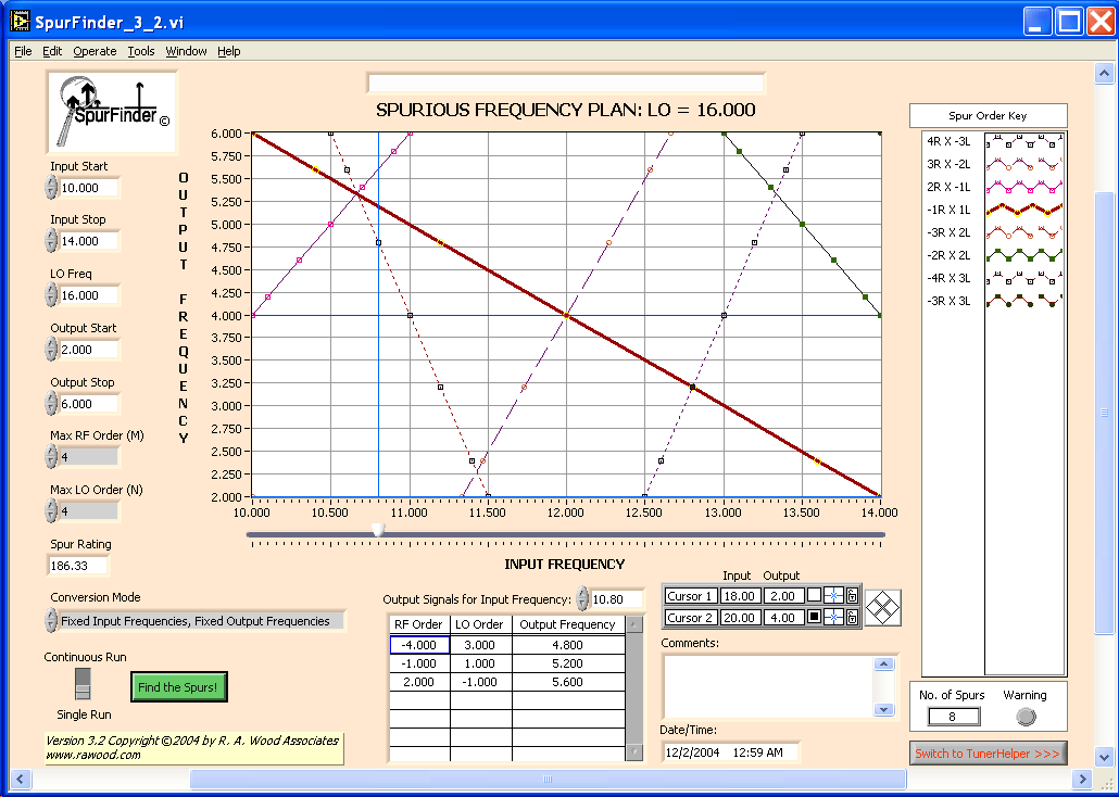
This is a 1024 X 768 resolution screen display of the SpurFinder interface. All input parameters are entered directly on the screen.

This plot shows the spurious frequencies for an example mixer down conversion. The input frequency band is 10.0 to 14.0 GHz. The output frequency band is 2.0 to 6.0 GHz. The LO is 16.0 GHz. The plot shows the location of all spurious products up to 4 X RF and 4 X LO. As the Input Frequency bar is moved across the input frequency band, the table updates the output signals and spurious products.
For example, if an input signal of 10.8 GHz (blue vertical line) is applied, the following spurs will show up at the output of the mixer:
-4*RF X 3*LO at 4.8 GHz Output Frequency
2*RF X -1*LO at 5.6 GHz Output Frequency
-1*RF X 1*LO at 5.2 GHz (this is probably the desired signal)
Spur Line Weights:
Notice how the each spur line is drawn. The larger (higher level) products have thicker lines, starting with the 1*RF X 1*LO products. Based on typical mixer spur products, the various mixer products are designated with different weight lines as follows:
Solid Thick Lines: +/-(0, 1)*RF +/-(0, 1)*LO products (main signals and images, and very high level spurs) Solid Thin Lines: Next Higher Spurs Long Dashed Lines: Lower Spurs Shorter Dashed Lines: Lower, Lower Spurs Shortest Dashed Lines: Lowest Spurs
These lines should give the user a rough idea of the levels of the spur products, For more accurate predictions, switch to TunerHelper, and define the actual mixer spur levels for a given mixer. The actual mixer spur levels can be set up based on measurements or vendor catalog data.